Download presentation
Presentation is loading. Please wait.

2
Delay models (I) A B C Real (analog) behaviorAbstract behavior A B C Abstractions are necessary to define delay models manageable for design, synthesis and verification. Abstractions introduce optimistic and pessimistic simplifications that must be carefully taken into account.

3
Delay models (II) Separation between functionality and timing [Muller] Every gate has a zero-delay atomic evaluator (Boolean function) A delay is associated to every output (gate delay model) or every input (wire delay model) Delays can be: Unbounded (arbitrary finite delays) Bounded (within given min/max bounds) Gate delay model Wire delay model
![Delay models (II) Separation between functionality and timing [Muller] Every gate has a zero-delay atomic evaluator (Boolean function) A delay is associated to every output (gate delay model) or every input (wire delay model) Delays can be: Unbounded (arbitrary finite delays) Bounded (within given min/max bounds) Gate delay model Wire delay model](http://images.slideplayer.com/7/1652286/slides/slide_3.jpg "Delay models (II) Separation between functionality and timing [Muller] Every gate has a zero-delay atomic evaluator (Boolean function) A delay is associated to every output (gate delay model) or every input (wire delay model) Delays can be: Unbounded (arbitrary finite delays) Bounded (within given min/max bounds) Gate delay model Wire delay model")
4
Delay models (III) Gate delay model: delays in gates, no delays in wires Wire delay model: delays in gates and wires
 Gate delay model: delays in gates, no delays in wires Wire delay model: delays in gates and wires")
5
Delay models (IV) Speed-independent circuit Speed-independent circuit: hazard-free under the unbounded gate delay model Delay-insensitive circuit Delay-insensitive circuit: hazard-free under the unbounded wire delay model Quasi-delay -insensitive circuit Quasi-delay -insensitive circuit: delay-insensitive with some isochronic forks
 Speed-independent circuit Speed-independent circuit: hazard-free under the unbounded gate delay model Delay-insensitive circuit Delay-insensitive circuit: hazard-free under the unbounded wire delay model Quasi-delay -insensitive circuit Quasi-delay -insensitive circuit: delay-insensitive with some isochronic forks")
6
Speed-independent model Pessimistic, since delays are typically bounded Optimistic, since it assumes isochronic forks (negligible skew wrt the receiving gate delays) Efficient synthesis methods exist Isochronic fork
 Efficient synthesis methods exist Isochronic fork")
7
Fundamental mode of operation Circuit Inputs Outputs [Huffman 1964] : The circuit/environment interact with two phases (1) The environment sends inputs to the circuit (2) The circuit computes the outputs and the state signals The environment does not send new inputs until the circuit stabilizes Normal Fundamental Mode: Only one input changes at each communication cycle
![Fundamental mode of operation Circuit Inputs Outputs [Huffman 1964] : The circuit/environment interact with two phases (1) The environment sends inputs to the circuit (2) The circuit computes the outputs and the state signals The environment does not send new inputs until the circuit stabilizes Normal Fundamental Mode: Only one input changes at each communication cycle](http://images.slideplayer.com/7/1652286/slides/slide_7.jpg "Fundamental mode of operation Circuit Inputs Outputs [Huffman 1964] : The circuit/environment interact with two phases (1) The environment sends inputs to the circuit (2) The circuit computes the outputs and the state signals The environment does not send new inputs until the circuit stabilizes Normal Fundamental Mode: Only one input changes at each communication cycle")
8
Input/Output mode of operation Computation and communication can overlap (according to some specified protocol) Event-based specification models are often used to describe the behavior (e.g., Petri nets). This tutorial will cover the synthesis of speed-independent circuits that work under the I/O mode of operation and are specified using Petri nets.

9
Delay models for async. circuits Bounded delays (BD): realistic for gates and wires. Technology mapping is easy, verification is difficult Speed independent (SI): Unbounded (pessimistic) delays for gates and negligible (optimistic) delays for wires. Technology mapping is more difficult, verification is easy Delay insensitive (DI): Unbounded (pessimistic) delays for gates and wires. DI class (built out of basic gates) is almost empty Quasi-delay insensitive (QDI): Delay insensitive except for critical wire forks (isochronic forks). In practice it is the same as speed independent BD SI QDI DI
: Unbounded (pessimistic) delays for gates and negligible (optimistic) delays for wires. Technology mapping is more difficult, verification is easy Delay insensitive (DI): Unbounded (pessimistic) delays for gates and wires. DI class (built out of basic gates) is almost empty Quasi-delay insensitive (QDI): Delay insensitive except for critical wire forks (isochronic forks). In practice it is the same as speed independent BD SI QDI DI.")
10
Outline Overview of the synthesis flow Specification State graph and next-state functions State encoding Implementability conditions Speed-independent circuit Complex gates C-element architecture Review of some advanced topics

11
Book and synthesis tool J. Cortadella, M. Kishinevsky, A. Kondratyev, L. Lavagno and A. Yakovlev, Logic synthesis for asynchronous controllers and interfaces, Springer-Verlag, 2002 petrify: http://www.lsi.upc.es/petrify

12
Design flow Specification (STG) State Graph SG with CSC Next-state functions Decomposed functions Gate netlist Reachability analysis State encoding Boolean minimization Logic decomposition Technology mapping
 State Graph SG with CSC Next-state functions Decomposed functions Gate netlist Reachability analysis State encoding Boolean minimization Logic decomposition Technology mapping")
13
Specification x y z x+ x- y+ y- z+ z- Signal Transition Graph (STG) x y z
 x y z")
14
Token flow x y z x+ x- y+ y- z+ z-

15
State graph x+ x- y+ y- z+ z- xyz 000 x+ 100 y+ z+ y+ 101 110 111 x- 001 011 y+ z- 010 y-

16
Next-state functions xyz 000 x+ 100 y+ z+ y+ 101 110 111 x- 001 011 y+ z- 010 y-

17
Gate netlist x z y

18
Design flow Specification (STG) State Graph SG with CSC Next-state functions Decomposed functions Gate netlist Reachability analysis State encoding Boolean minimization Logic decomposition Technology mapping
 State Graph SG with CSC Next-state functions Decomposed functions Gate netlist Reachability analysis State encoding Boolean minimization Logic decomposition Technology mapping")
19
VME bus Device LDS LDTACK D DSr DSw DTACK VME Bus Controller Data Transceiver Bus DSr LDS LDTACK D DTACK Read Cycle

20
STG for the READ cycle LDS+LDTACK+D+DTACK+DSr-D- DTACK- LDS-LDTACK- DSr+ LDS LDTACK D DSr DTACK VME Bus Controller

21
Choice: Read and Write cycles DSr+ LDS+ LDTACK+ D+ DTACK+ DSr- D- DTACK- LDS- LDTACK- DSw+ D+ LDS+ LDTACK+ D- DTACK+ DSw- DTACK- LDS- LDTACK-

22
Choice: Read and Write cycles DTACK- DSr+ LDS+ LDTACK+ D+ DTACK+ DSr- D- LDS- LDTACK- DSw+ D+ LDS+ LDTACK+ D- DTACK+ DSw-

23
Circuit synthesis Goal: Derive a hazard-free circuit under a given delay model and mode of operation

24
Speed independence Delay model Unbounded gate / environment delays Certain wire delays shorter than certain paths in the circuit Conditions for implementability: Consistency Complete State Coding Persistency

25
Design flow Specification (STG) State Graph SG with CSC Next-state functions Decomposed functions Gate netlist Reachability analysis State encoding Boolean minimization Logic decomposition Technology mapping
 State Graph SG with CSC Next-state functions Decomposed functions Gate netlist Reachability analysis State encoding Boolean minimization Logic decomposition Technology mapping")
26
STG for the READ cycle LDS+LDTACK+D+DTACK+DSr-D- DTACK- LDS-LDTACK- DSr+ LDS LDTACK D DSr DTACK VME Bus Controller

27
Binary encoding of signals DSr+ DTACK- LDS- LDTACK- D- DSr-DTACK+ D+ LDTACK+ LDS+

28
Binary encoding of signals DSr+ DTACK- LDS- LDTACK- D- DSr-DTACK+ D+ LDTACK+ LDS+ 10000 10010 10110 0111001110 01100 00110 10110 (DSr, DTACK, LDTACK, LDS, D)
")
29
Excitation / Quiescent Regions QR (LDS+) QR (LDS-) ER (LDS+) ER (LDS-) LDS- LDS+ LDS-
 QR (LDS-) ER (LDS+) ER (LDS-) LDS- LDS+ LDS-")
30
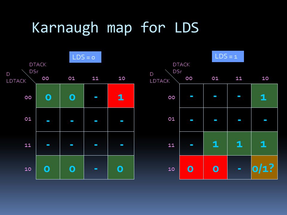
Next-state function 0 1 LDS- LDS+ LDS- 1 0 0 1 10110

31
Karnaugh map for LDS DTACK DSr D LDTACK 00011110 00 01 11 10 DTACK DSr D LDTACK 00011110 00 01 11 10 LDS = 0 LDS = 1 01-0 000000/1? 1 111 - - - --- ---- - ---- ---
32
Design flow Specification (STG) State Graph SG with CSC Next-state functions Decomposed functions Gate netlist Reachability analysis State encoding Boolean minimization Logic decomposition Technology mapping
 State Graph SG with CSC Next-state functions Decomposed functions Gate netlist Reachability analysis State encoding Boolean minimization Logic decomposition Technology mapping")
33
Concurrency reduction LDS- LDS+ LDS- 10110 DSr+

34
Concurrency reduction LDS+LDTACK+D+DTACK+DSr-D- DTACK- LDS-LDTACK- DSr+

35
State encoding conflicts LDS- LDTACK- LDTACK+ LDS+ 10110

36
Signal Insertion LDS- LDTACK- D- DSr- LDTACK+ LDS+ CSC- CSC+ 101101 101100

37
Design flow Specification (STG) State Graph SG with CSC Next-state functions Decomposed functions Gate netlist Reachability analysis State encoding Boolean minimization Logic decomposition Technology mapping
 State Graph SG with CSC Next-state functions Decomposed functions Gate netlist Reachability analysis State encoding Boolean minimization Logic decomposition Technology mapping")
38
Complex-gate implementation

39
Implementability conditions Consistency Rising and falling transitions of each signal alternate in any trace Complete state coding (CSC) Next-state functions correctly defined Persistency No event can be disabled by another event (unless they are both inputs)
 Next-state functions correctly defined Persistency No event can be disabled by another event (unless they are both inputs)")
40
Implementability conditions Consistency + CSC + persistency There exists a speed-independent circuit that implements the behavior of the STG (under the assumption that ay Boolean function can be implemented with one complex gate)
")
41
Persistency 100000001 a- c+ b+b+ b+b+ a c b a c b is this a pulse ? Speed independence glitch-free output behavior under any delay

42
a+ b+ c+ d+ a- b- d- a+ c-a- 0000 1000 1100 0100 0110 0111 1111 10111011 00111001 0001 a+ b+ c+ a- b- c- a+ c- a- d- d+

43
0000 1000 1100 0100 0110 0111 1111 10111011 00111001 0001 a+ b+ c+ a- b- c- a+ c- a- d- d+ ab cd 00011110 00 01 11 10 1 11 11 1 0 0000 ER(d+) ER(d-)
 ER(d-)")
44
ab cd 00011110 00 01 11 10 1 11 11 1 0 0000 0000 1000 1100 0100 0110 0111 1111 10111011 00111001 0001 a+ b+ c+ a- b- c- a+ c- a- d- d+ Complex gate

45
Implementation with C elements C R S z S+ z+ S- R+ z- R- S (set) and R (reset) must be mutually exclusive S must cover ER(z+) and must not intersect ER(z-) QR(z-) R must cover ER(z-) and must not intersect ER(z+) QR(z+)
 and R (reset) must be mutually exclusive S must cover ER(z+) and must not intersect ER(z-) QR(z-) R must cover ER(z-) and must not intersect ER(z+) QR(z+)")
46
ab cd 00011110 00 01 11 10 1 11 11 1 0 0000 0000 1000 1100 0100 0110 0111 1111 10111011 00111001 0001 a+ b+ c+ a- b- c- a+ c- a- d- d+ C S R d

47
0000 1000 1100 0100 0110 0111 1111 10111011 00111001 0001 a+ b+ c+ a- b- c- a+ c- a- d- d+ C S R d but...

48
0000 1000 1100 0100 0110 0111 1111 10111011 00111001 0001 a+ b+ c+ a- b- c- a+ c- a- d- d+ C S R d Assume that R=ac has an unbounded delay Starting from state 0000 (R=1 and S=0): a+ ; R- ; b+ ; a- ; c+ ; S+ ; d+ ; R+ disabled (potential glitch)
: a+ ; R- ; b+ ; a- ; c+ ; S+ ; d+ ; R+ disabled (potential glitch)")
49
ab cd 00011110 00 01 11 10 1 11 11 1 0 0000 0000 1000 1100 0100 0110 0111 1111 10111011 00111001 0001 a+ b+ c+ a- b- c- a+ c- a- d- d+ C S R d Monotonic covers

50
C-based implementations C S R d C d a b c a b c d weak a c d generalized C elements (gC) weak
 weak")
51
Speed-independent implementations Implementability conditions Consistency Complete state coding Persistency Circuit architectures Complex (hazard-free) gates C elements with monotonic covers...
 gates C elements with monotonic covers...")
52
Synthesis exercise y- z-w- y+x+ z+ x- w+ 1011 0111 0011 1001 1000 1010 0001 00000101 00100100 0110 y- y+ x- x+ w+ w- z+ z- w- z- y+ x+ Derive circuits for signals x and z (complex gates and monotonic covers)
")
53
Synthesis exercise 1011 0111 0011 1001 1000 1010 0001 00000101 00100100 0110 y- y+ x- x+ w+ w- z+ z- w- z- y+ x+ wx yz 00011110 00 01 11 10 - - - - Signal x 1 0 1 1 1 1 1 0 0 0 0 0

54
Synthesis exercise 1011 0111 0011 1001 1000 1010 0001 00000101 00100100 0110 y- y+ x- x+ w+ w- z+ z- w- z- y+ x+ wx yz 00011110 00 01 11 10 - - - - Signal z 1 0 0 0 0 1 1 1 0 0 0 0

55
Logic decomposition: example y- z-w- y+x+ z+ x- w+ 10011011 1000 1010 0001 00000101 00100100 01100111 0011 y- y+ x- x+ w+ w- z+ z- w- z- y+ x+

56
Logic decomposition: example yz=1 yz=0 10011011 1000 1010 0001 00000101 00100100 01100111 0011 y- y+ x- x+ w+ w- z+ z- w- z- y+ x+ 10011011 1000 1010 0001 00000101 00100100 01100111 0011 y- y+ x- x+ w+ w- z+ z- w- z- y+ x+ C C x y x y w z x y z y z w z w z y

57
Logic decomposition: example s- s+ s- s=1 s=0 10011011 1000 1010 0111 0011 y+ x- w+ z+ z- 0001 00000101 00100100 0110 x+ w- z- y+ x+ 1001 1000 1010 y+ z- 0111 C C x y x y w z x y z w z w z y s y-

58
Logic decomposition: example y- z-w- y+x+ z+ x- w+ s- s+ s- s+ s- s=1 s=0 10011011 1000 1010 0111 0011 y+ x- w+ z+ z- 0001 00000101 00100100 0110 x+ w- z- y+ x+ 1001 1000 1010 y+ z- 0111 y-

59
Speed-independent Netlist LDS+LDTACK+D+DTACK+DSr-D- DTACK- LDS-LDTACK- DSr+ DTACK D DSr LDS LDTACK csc map

60
Adding timing assumptions LDS+LDTACK+D+DTACK+DSr-D- DTACK- LDS-LDTACK- DSr+ DTACK D DSr LDS LDTACK csc map LDTACK- before DSr+ FAST SLOW

61
Adding timing assumptions DTACK D DSr LDS LDTACK csc map LDS+LDTACK+D+DTACK+DSr-D- DTACK- LDS-LDTACK- DSr+ LDTACK- before DSr+

62
State space domain LDTACK- before DSr+ LDTACK- DSr+

63
State space domain LDTACK- before DSr+ LDTACK- DSr+

64
State space domain LDTACK- before DSr+ LDTACK- DSr+ Two more unreachable states

65
Boolean domain DTACK DSr D LDTACK 00011110 00 01 11 10 DTACK DSr D LDTACK 00011110 00 01 11 10 LDS = 0 LDS = 1 01-0 000000/1? 1 111 - - - --- ---- - ---- ---

66
Boolean domain DTACK DSr D LDTACK 00011110 00 01 11 10 DTACK DSr D LDTACK 00011110 00 01 11 10 LDS = 0 LDS = 1 01-0 00-001 1 111 - - - --- ---- - ---- --- One more DC vector for all signalsOne state conflict is removed

67
Netlist with one constraint LDS+LDTACK+D+DTACK+DSr-D- DTACK- LDS-LDTACK- DSr+ DTACK D DSr LDS LDTACK csc map

68
Netlist with one constraint LDS+LDTACK+D+DTACK+DSr-D- DTACK- LDS-LDTACK- DSr+ DTACK D DSr LDS LDTACK LDTACK- before DSr+ TIMING CONSTRAINT

69
Signal insertion New signals need to be inserted to solve some synthesis problems (e.g., state encoding, logic decomposition) For each signal s, the events s+ and s- must be inserted while preserving certain behavioral properties (consistency, persistency). Each new signal determines a new partition of states (s=0, s=1)
.")
70
Signal insertion s=0s=1 s+ s-

71
From state graphs to Petri nets A state graph may require transformations to meet certain properties (e.g., state encoding). The visualization of a state graph is not very informative. Event-based specifications explicitly represent the relations between events. Resort to the theory of regions

72
From state graphs to Petri nets 01 2 3 4 5 6 a b c c d d e e f f d a b c d ef Region: {2,3}

73
From state graphs to Petri nets 01 2 3 4 5 6 a b c c d d e e f f d a b c d ef Region: {1}

74
From state graphs to Petri nets 01 2 3 4 5 6 a b c c d d e e f f d a b c d ef Not a region: {3,5}

75
From state graphs to Petri nets 01 2 3 4 5 6 a b c c d d e e f f d a b c d ef Region: {0,3,5}

76
Theory of regions Region: all arcs of any event have the same relationship with the region (enter, exit, no cross). Minimal region: not included in any other region Pre-/post-region of an event: region such that the event exits/enters the region Property: excitation closure The intersection of all pre-regions of an event is the excitation region of the event

77
Thanks to Steve Nowick (Columbia Univ.)
")
78
Burst-Mode Specifications How to specify burst-mode behavior?: Hazard-Free Combinational Network inputs outputs state (several bits) A B C X Y Z input burst output burst A+ C-/ Y- Z+ 1 current state input burst/ output burst 2 next state
 A B C X Y Z input burst output burst A+ C-/ Y- Z+ 1 current state input burst/ output burst 2 next state")
79
Note: -input bursts: must be non-empty (at least 1 input per burst) -output bursts: may be empty (0 or more outputs per burst) Burst-Mode Specifications Example: Burst-Mode (BM) Specification: - Inputs in specified input burst can arrive in any order and at any time - After all inputs arrive, generate output burst 0132 4 5 A+ C+/ Z- C-/ Z+ C+/ Y+ A-/ Y- A+ B+/ Y+ Z- B- C+/ Z+ C-/ -- Initial Values: ABC = 000 YZ = 01
 -output bursts: may be empty (0 or more outputs per burst) Burst-Mode Specifications Example: Burst-Mode (BM) Specification: - Inputs in specified input burst can arrive in any order and at any time - After all inputs arrive, generate output burst A+ C+/ Z- C-/ Z+ C+/ Y+ A-/ Y- A+ B+/ Y+ Z- B- C+/ Z+ C-/ -- Initial Values: ABC = 000 YZ = 01")
80
Burst-Mode Specifications Extended Burst-Mode (XBM): [Yun/Dill ICCAD-93/95] 1. directed dont cares (Rin*): allow concurrent inputs & outputs 2. conditionals ( ): allow sampling of level signals Handles glitchy inputs, mixed sync/async inputs, etc. 0123456 ok+ Rin*/ FRout+ FAin+ Rin*/ FRout- FAin- Rin+/ Aout+ Rin* FAin+/ FRout- Rin-/ Aout- FRout+ Rin-/ Aout- ok- Rin*/ -- Rin+ FAin-/ Aout+ New Features:
![Burst-Mode Specifications Extended Burst-Mode (XBM): [Yun/Dill ICCAD-93/95] 1.](http://images.slideplayer.com/7/1652286/slides/slide_80.jpg "directed dont cares (Rin*): allow concurrent inputs & outputs 2. conditionals ( ): allow sampling of level signals Handles glitchy inputs, mixed sync/async inputs, etc ok+ Rin*/ FRout+ FAin+ Rin*/ FRout- FAin- Rin+/ Aout+ Rin* FAin+/ FRout- Rin-/ Aout- FRout+ Rin-/ Aout- ok- Rin*/ -- Rin+ FAin-/ Aout+ New Features:.")
81
Syntax-directed translation 2-Place Ripple Register (= FIFO) [van Berkel] proc (a?T & b!T) begin x0, x1: var T | forever do b! x1; x1 := x0; a? x0 od end Tangram Program Intermediate Handshake Circuit
![Syntax-directed translation 2-Place Ripple Register (= FIFO) [van Berkel] proc (a T & b!T) begin x0, x1: var T | forever do b.](http://images.slideplayer.com/7/1652286/slides/slide_81.jpg "x1; x1 := x0; a. x0 od end Tangram Program Intermediate Handshake Circuit.")
82
A Larger Example Intermediate Handshake Circuit

83
Components communicate using 4-phase handshaking O1: initiates communication O2: completes communication Channel impltn. => use 2 wires: req => start operation ack => operation done (… can be extended to handle data) Background: Channel-Based Communication O1O2 Channel A req ack Active phase Return-to-zero (RTZ) phase passive port active port
 Background: Channel-Based Communication O1O2 Channel A req ack Active phase Return-to-zero (RTZ) phase passive port active port.")
84
Handshake Components: Sequencer 2-Way Sequencer: activated on channel P; then activates 2 processes in sequence on channels A1 and A2 P A1 SEQ A2 Goal: Goal: activate two sequential processes (i.e. operations) Process X1 Process X2 Operation X1; X2
 Process X1 Process X2 Operation X1; X2.")
85
Handshake Components: PAR Component PAR Component: activated on channel P; then activates 2 processes in parallel on channels A1 and A2 P A1 PAR A2 Goal: Goal: activate two parallel processes Process X1 Process X2 Operation X1 || X2

86
procedure Buf1 ( input i: byte; output o: byte) is local variable x : byte begin loop begin i -> x ; o <- x end Intermediate Representation ; #Start X I O Tangram Spec Handshake Circuit Syntax-Directed Translation unoptimized
 is local variable x : byte begin loop begin i -> x ; o <- x end Intermediate Representation ; #Start X I O Tangram Spec Handshake Circuit Syntax-Directed Translation unoptimized")
87
Conclusions STGs have a high expressiveness power at a low level of granularity (similar to FSMs for synchronous systems) Synthesis from STGs can be fully automated Synthesis tools often suffer from the state explosion problem (symbolic techniques are used) The theory of logic synthesis from STGs can be found in: J. Cortadella, M. Kishinevsky, A. Kondratyev, L. Lavagno and A. Yakovlev, Logic Synthesis of Asynchronous Controllers and Interfaces, Springer Verlag, 2002.

Similar presentations


>")
 Logic Minimization CD AB 00011110 00 01 11 10 F = Σm(0,6,7,8,9,11,15) + d(1,13)>")


 Optimization State tables State minimization State assignment Combinational logic optimization.>")


>")


