Download presentation
Presentation is loading. Please wait.

1
3-Phase Submersible Motor Control

2
SubMonitor Features One unit for all ratings
190 to 600 VAC 50 and 60 Hz Motor ratings from 3 to 359 amps (3 to 200 Hp) Continuously monitors & displays Voltage – all three legs Current – all three legs Pump status
 Continuously monitors & displays. Voltage – all three legs. Current – all three legs. Pump status.")
3
Easy to Install Enter motor nameplate data
Hz Volts Service Factor Amps Motor data can be entered anytime Before installation in panel Wall outlet transformer After installation

4
User-Friendly Features
Detachable Display Mount on front of panel NEMA 3R rated Integrated current transformers No external CT’s to add No additional turns of wire to calculate DIN rail mounting UL 508 Listed

5
SubMonitor Advanced Features
Event history log Pump run time counter >500 events recorded Faults Setting changes Power interruptions Manual resets Password protected settings Optional

6
Pump / Motor Protection
Protects against Overload Underload Under/Overvoltage Current Unbalance Overheated Motor (Subtrol-Equipped) False Start (Chattering relays) Phase Reversal (reverse rotation)
 False Start (Chattering relays) Phase Reversal (reverse rotation)")
7
Two Package Versions SubMonitor Premium Package
Lightning Arrestor 3-year SubMonitor warranty 3-year FE Motor warranty Panel Door Mounting Kit SubMonitor Standard Unit 1-year warranty

8
Warranty Policy 3-Year Warranty
3 years from installation not to exceed 4 years from SubMonitor date code Requirements: Simultaneous installation of SubMonitor, Subtrol-Equipped Motor, Lightning Arrestor Completed warranty card submitted within 30 days of installations Covers motor and SubMonitor Warranty on replacement units is the period remaining on the 3-year warranty or the standard warranty, whichever is longer

9
Components

10
Easy to Install

11
Wiring

12
Wiring General Panel Configuration Contactor M1, M2 SubMonitor
Alarm Circuit is not represented Contactor M1, M2 SubMonitor Connections To Contactor Coil T1 T2 T3

13
Wiring – External Alarm
Alarm circuit Lamp dialer 115 or 230 Volt Power External Source or Control Power Transformer M1 M2 A1 A2

14
SubMonitor Installations
Easy Set-up Simple text in display area One menu level to set-up motor for commissioning Simple intuitive interactive push/turn knob

15
Special Conditions The SubMontior is NOT COMPATIABLE with variable frequency drives, electric phase converters, or soild state soft starters…….cause nuisance tripping of the motor overheat fault. Reduced-voltage starters may be used with SubMontior if thewy are bypassed. 2 sec Maximum due to the 3 sec reaction time of SubMonitor

16
Other Applications Surface motors
Reference amps should be Full Load Amps Rotation may be different than FE Submersible motors (Phase Reversal Trip Feature) SubMonitor does not employ trip class (current vs time curves)
 SubMonitor does not employ trip class (current vs time curves)")
17
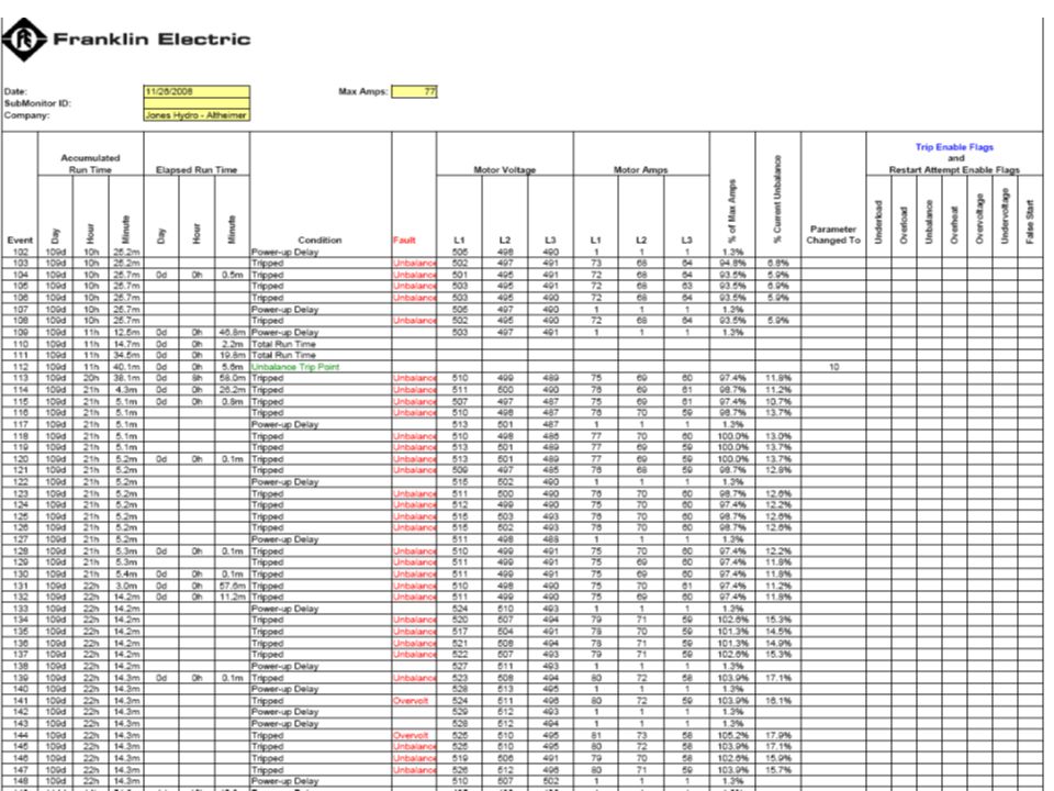
D3 Service tool Provides the ability to download data from the SubMonitor and upload that data to a PC Software included with D3 USB Cable Connector provided Easy to use .xls file format for spreadsheet format

19
SubMonitor Installations

20
Thank you!

Similar presentations


>")


