Download presentation
Presentation is loading. Please wait.

4
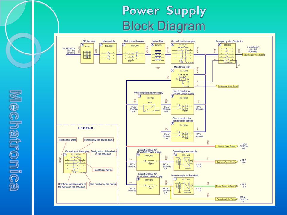
Graphic Symbol Location 1. DIN Terminal X52 The machine is powered by electricity using copper cable with 5 wires (3 phase wires + neutral wire + ground wire). The thickness of the wires should be at least 4mm 2 (5 x 4mm 2 ). The power cable is connected to a DIN terminal block X52, located at the bottom of the main cabinet. The machine is protected within enclosures rated at IP20 (protection against the solid objects larger than 12mm). When the machine is supplied with 4-wire cable make a bridge (short circuit) between the blue and green terminals of the terminal block X52. X52
. The thickness of the wires should be at least 4mm 2 (5 x 4mm 2 ). The power cable is connected to a DIN terminal block X52, located at the bottom of the main cabinet. The machine is protected within enclosures rated at IP20 (protection against the solid objects larger than 12mm). When the machine is supplied with 4-wire cable make a bridge (short circuit) between the blue and green terminals of the terminal block X52. X52.")
5
Graphic Symbol Location 2. MAIN SWITCH The main power switch of the machine is a cam-type rotary switch. Turn ON Turn the switch in a clockwise direction until the knob stands in a vertical position, the contacts are now closed and electricity is supplied to the machine. Turn OFF Turn the switch in a counterclockwise direction until the knob sits in a horizontal position, the contacts are now open and the electricity supply to the machine is stopped.

6
Graphic Symbol Location 3. MAIN CIRCUIT BREAKER The main circuit breaker is an automatic three-pole switch (3x400V / 25A). It is located on the bottom row within the main cabinet of the machine. PURPOSE To protect the electrical circuits of the machine from short-circuit currents. To protect electrical circuits from overloading (working currents above 25A). To disconnect the wiring of the machine from the power network. Note: If the main circuit breaker TURNS OFF automatically, call an electrician to investigate and remedy the cause!
. It is located on the bottom row within the main cabinet of the machine. PURPOSE To protect the electrical circuits of the machine from short-circuit currents. To protect electrical circuits from overloading (working currents above 25A). To disconnect the wiring of the machine from the power network. Note: If the main circuit breaker TURNS OFF automatically, call an electrician to investigate and remedy the cause!.")
7
Graphic Symbol Location 4. GROUND FAULT INTERRUPTER Located on the second row within the main cabinet of the machine. Purpose: To protect people and property against direct and indirect contact with current- conductive parts of the machine. To prevent currents leaking from the machine. To turn off the power network to the machine in case of a voltage leak to the metal housing. To turn off the power network to the machine in case of fire. Attention: The metal casing of the machine must be grounded for the ground fault interrupter to work properly. Note: If the ground fault interrupter TURNS OFF automatically, call an electrician to investigate and remedy the cause!

8
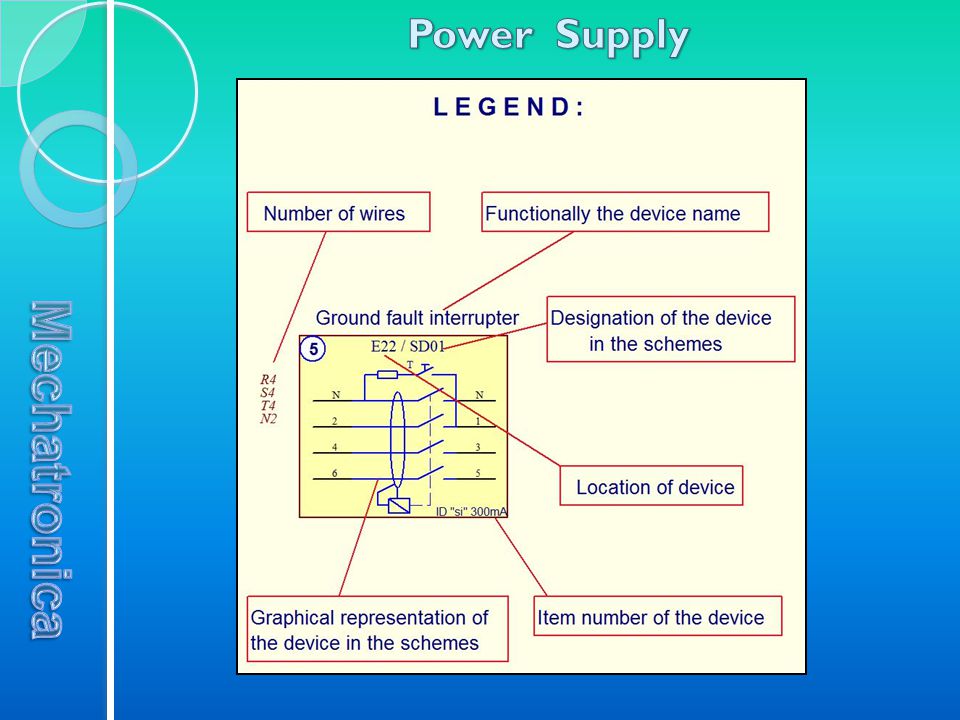
Graphic Symbol Location 5. MONITORING RELAY Located on the second row within the main cabinet of the machine. The monitoring relay is a device for measuring electrical parameters of the phase voltages. When it detects a change outside its thresholds the monitoring relay interrupts power to the machine’s actuators. The KOMBIS TMM8003’s monitoring relay has the monitors the following functions: voltage of the 3-phase mains with adjustable thresholds ( MIN and MAX ) phase sequence and phase or neutral failure monitoring of the asymmetry with adjustable threshold ( ASYM ) adjustable tripping delay.
 phase sequence and phase or neutral failure monitoring of the asymmetry with adjustable threshold ( ASYM ) adjustable tripping delay..")
9
The following controls are located within the main cabinet on the second row, next to the ground fault interrupter (from right to left): Emergency stop switch [6] Circuit breakers for the power supply [8] and for luminescent lighting [9] (two-poles). Circuit breaker [11] for the operating power supply unit. The power supply converts 220VAC into 24VDC used by sensors and valves, control buttons and switches and other low power devices. Circuit breaker [13] for the controllers power supply units (main controller "Beckhoff" and motion controller "Trajexia"). 6 89 11 13
![The following controls are located within the main cabinet on the second row, next to the ground fault interrupter (from right to left): Emergency stop switch [6] Circuit breakers for the power supply [8] and for luminescent lighting [9] (two-poles).](http://images.slideplayer.com/14/4246260/slides/slide_9.jpg "Circuit breaker [11] for the operating power supply unit. The power supply converts 220VAC into 24VDC used by sensors and valves, control buttons and switches and other low power devices. Circuit breaker [13] for the controllers power supply units (main controller Beckhoff and motion controller Trajexia )")
10
Graphic Symbol Location 6. UPS unit Uninterruptible Power Supply unit (UPS) is an intelligent electrical device that provides emergency power to the loads by supplying energy stored in batteries, when the input power source (mains power) fails. The on-battery runtime uninterruptible energy is relatively short (only a few minutes) but sufficient to start a standby power source or properly shut down the protected equipment. The KOMBIS 8003’s UPS protects the Control Voltage which supplies the control system and sensing devices of the machine. When the mains power is interrupted the main controller initiates a shut down and turn-off procedure, during this time the machine's monitor displays a "POWER OFF“ error message.
 is an intelligent electrical device that provides emergency power to the loads by supplying energy stored in batteries, when the input power source (mains power) fails. The on-battery runtime uninterruptible energy is relatively short (only a few minutes) but sufficient to start a standby power source or properly shut down the protected equipment. The KOMBIS 8003’s UPS protects the Control Voltage which supplies the control system and sensing devices of the machine. When the mains power is interrupted the main controller initiates a shut down and turn-off procedure, during this time the machine s monitor displays a POWER OFF error message..")
11
Graphic Symbol Location 7. Operating Power Supply unit This is a device that converts mains electricity of 110-240VAC to a lower direct and stabilized voltage of 24VDC. The device can supply 320 watts of power. It is equipped with electronic protection from short circuits in its output and a trimmer to adjust the output voltage range from 22 to 26 volts. Voltage produced by this device is called the Operating Voltage. This voltage supplies all electrical components that require 24VDC, participating in the drives, the control and the diagnostic of the machine. These are: all sensors, solenoid valves, relays, switches, control units, stepper motors, signal lamps, etc. It is located at the left side of the machine’s main cabinet.

12
ProblemCauseRemedy 1. The computer does not start after turning on the main switch QS01 1.1. There is no mains power supply. 1.2. The main circuit breaker QF01 is turned off. 1.3. The ground fault interrupter SD01 is switched off. 1.4. The circuit breaker of the UPS input (QF02) is switched off. 1.5. The UPS is turned off. 1.6. The UPS’s output cable connector is not fully inserted (or removed). 1.7. The controller’s power supply circuit breaker (QF21) is switched off. 1.1. Check the voltage at the input DIN terminal X52. 1.2. Turn on the main circuit breaker. 1.3. Check for leakage current and then turn on SD01. 1.4. Turn on QF02. 1.5. Turn on the UPS. 1.6. Insert the cable connector. 1.7. Turn on the circuit breaker QF21. 2. After switching on the UPS there are no LED’s lit on its front panel. 2.1. The battery is exhausted. 2.2. The battery is defective. 2.3. The UPS is damaged. 2.1. The UPS must be left to charge for at least 10 hours. 2.2. Replace with a new battery of the same type. 2.3. Replace with a new UPS (or one repaired by a qualified engineer). 3. The UPS unit emits a continuous “BEEP” signal. 3.1. Load too high in the circuits of the control power supply (wires No: S21, N21). 3.2. Short circuit in the control power supply (wires No: S21, N21). 3.1. Measured impedance of the control power supply (it must be more than 1000 Ohms) and remove the critical load. 3.2. The remove the short circuit.
 is switched off The UPS is turned off The UPS’s output cable connector is not fully inserted (or removed) The controller’s power supply circuit breaker (QF21) is switched off Check the voltage at the input DIN terminal X Turn on the main circuit breaker Check for leakage current and then turn on SD Turn on QF Turn on the UPS Insert the cable connector Turn on the circuit breaker QF After switching on the UPS there are no LED’s lit on its front panel The battery is exhausted The battery is defective The UPS is damaged The UPS must be left to charge for at least 10 hours Replace with a new battery of the same type Replace with a new UPS (or one repaired by a qualified engineer). 3. The UPS unit emits a continuous BEEP signal Load too high in the circuits of the control power supply (wires No: S21, N21) Short circuit in the control power supply (wires No: S21, N21) Measured impedance of the control power supply (it must be more than 1000 Ohms) and remove the critical load The remove the short circuit..")
13
ProblemCauseRemedy 4. With the mains power supply working the UPS unit emits a “BEEP” signal every 5 seconds. 4.1. A burnt fuse (automatic circuit breaker is switched off) in the UPS input. 4.2. The UPS’s input cable connector is not fully inserted (or removed). 4.1. Replaced it with the same kind (switch on the breaker). 4.2. Insert the cable connector. 5. The emergency stop switch K02 does not switch on when all emergency stop buttons are switched off (main power is interrupted ). 5.1. Some of the emergency stop buttons (red button-mushroom) are damaged. 5.2. The monitor relay KH01 has not been switched on (someone relays have red LED lights). 5.1. Find and replaced it. 5.2. 1. Red LED “SEQ” illuminated (phase sequence is detected or one of the phase voltages fails) - Measure the three phase voltages of the mains. If they are OK, swap the places of the two phase wires from the mains cable into terminal X52. 5.2.2. Red LED “MAX” or “MIN” illuminated (The mains voltage is outside of the adjusted range) - Measure the three phase voltages of the mains. If they are OK, check adjusted values of MAX and MIN potentiometers (they must be: MAX = +10%, MIN = -20%). 5.2.3. Red LED “ASYM” illuminated (loss of the mains neutral wire or there is asymmetry of the phase-to-phase voltages) - Call an electrician to check the cause.
 in the UPS input The UPS’s input cable connector is not fully inserted (or removed) Replaced it with the same kind (switch on the breaker) Insert the cable connector. 5. The emergency stop switch K02 does not switch on when all emergency stop buttons are switched off (main power is interrupted ) Some of the emergency stop buttons (red button-mushroom) are damaged The monitor relay KH01 has not been switched on (someone relays have red LED lights) Find and replaced it Red LED SEQ illuminated (phase sequence is detected or one of the phase voltages fails) - Measure the three phase voltages of the mains. If they are OK, swap the places of the two phase wires from the mains cable into terminal X Red LED MAX or MIN illuminated (The mains voltage is outside of the adjusted range) - Measure the three phase voltages of the mains. If they are OK, check adjusted values of MAX and MIN potentiometers (they must be: MAX = +10%, MIN = -20%) Red LED ASYM illuminated (loss of the mains neutral wire or there is asymmetry of the phase-to-phase voltages) - Call an electrician to check the cause..")
14
ProblemCauseRemedy (5. Continuation) 5.3. A connector X35 (to capping station module) or X07 (to unwinding module) is/are disconnected. 5.4. No operating power supply 24VDC. 5.5. Contactor K02 is damaged. 5.3. Connect it/them. 5.4. See problem 7. 5.5. Change with a new contactor of the same type. 6. The relay К 01 (for pneumatic and movement lock) does not switch on. 6.1. No running control program in the main controller (no signal 2107). 6.2. Black button-mushroom “MOVEMENT LOCK” pressed. 6.3. Red button-mushroom “EMERGENCY STOP” pressed. 6.4. No operating power supply 24VDC. 6.5. Relay K01 is damaged. 6.1. Run the control program (check signal 2107 – it must be ON). 6.2. Pull to release the button. 6.3. Push-twist to release the button. 6.4. See problem 7. 6.5. Replace with a new one. 7. No operating power supply 24VDC. 7.1. Circuit breaker for the operating power supply unit QF20 is switched off at the main cabinet. 7.2. One or more of the wires connected to the terminals of the power supply unit are broken (disconnected). 7.3. Short circuit in the 24VDC circuit. 7.4. The power supply unit is damaged. 7.1. Turn on the circuit breaker QF20. 7.2. Find and replaced (connect) it. 7.3. Find the fault and remove it. 7.4. Replace with new one (or one repaired by a qualified engineer).
 or X07 (to unwinding module) is/are disconnected No operating power supply 24VDC Contactor K02 is damaged Connect it/them See problem Change with a new contactor of the same type. 6. The relay К 01 (for pneumatic and movement lock) does not switch on No running control program in the main controller (no signal 2107) Black button-mushroom MOVEMENT LOCK pressed Red button-mushroom EMERGENCY STOP pressed No operating power supply 24VDC Relay K01 is damaged Run the control program (check signal 2107 – it must be ON) Pull to release the button Push-twist to release the button See problem Replace with a new one. 7. No operating power supply 24VDC Circuit breaker for the operating power supply unit QF20 is switched off at the main cabinet One or more of the wires connected to the terminals of the power supply unit are broken (disconnected) Short circuit in the 24VDC circuit The power supply unit is damaged Turn on the circuit breaker QF Find and replaced (connect) it Find the fault and remove it Replace with new one (or one repaired by a qualified engineer)..")
Similar presentations


/40GXC(Q) Service Training Sizes 18 and 24K.>")


 4Mechanical Air Leak- Down 4Mechanical Air Leak- Up 4Electronic Drift- Up/ Down 4Load Cell Operation 4Understanding.>")


 TJ8300 / TJ8500 Electrical Cabinet (EC)>")


