Download presentation
Presentation is loading. Please wait.

1
ULTRASONIC WELDING

2
Ultrasonic Welding Learning Activities View Slides; Lesson Objectives
Read Notes, Listen to lecture Do on-line workbook Lesson Objectives When you finish this lesson you will understand: Ultrasonic Welding Definition, Characteristics, Process & Applications Ultrasonic Power Generation Interfacial Interactions & Dissimilar Metals Welding Keywords: Ultrasonic Welding, Transducer, Sonotrode, Anvil

4
Definition of Ultrasonic Welding
A solid state welding process in which coalescence is produced at the faying surfaces by the application of high frequency vibratory energy while the work pieces are held together under moderately low static pressure.

5
Ultrasonic Welding Process
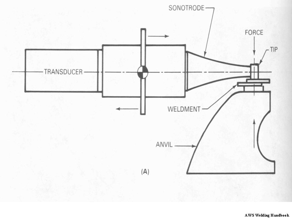
Clamping force Process Description: Components of ultrasonic welding system include: Transducer Sonotrode Anvil Mass wedge Transducer Sonotrode tip Typical components of an ultrasonic welding system are illustrated in the above figure. Linear ultrasonic vibrations are generated in the transducer and transferred to a sonotrode. The anvil holds the components in a fixed position and supports the clamping force. Vibration Weldment Anvil Force

6
Ultrasonic Welding Mechanism
Clamping force A static clamping force is applied perpendicular to the interface between the work pieces. The contacting sonotrode oscillates parallel to the interface. Combined effect of static and oscillating force produces deformation which promotes welding. Mass wedge Transducer Sonotrode tip 10-75 KHz workpiece Anvil Force

7
Process Variations Spot Welding Ring Welding
Line Welding - Linear Sonotrode Continuous Seam Welding - Roller Sonotrode Microminiature Welding

8
spot-type welding machine
Typical ultrasonic spot-type welding machine Courtesy AWS handbook

10
100 W Lateral Drive Ultrasonic Welder

11
Typical Ring Welding Applications
Tip in Shape of Weld

12
Attachment for Continuous Ring Welding

13
Tip Traversing Head for Continuous Seam Welding

14
Questions

15
Ultrasonic Welding Variables
Ultrasonic power Clamping force Welding time Frequency Linear Vibration Amplitude There are five variables in ultrasonic welding. They are : (a) Ultrasonic power (b) Clamping force (c) Welding time (d) Frequency (e) Amplitude of Linear Vibration
 Ultrasonic power. (b) Clamping force. (c) Welding time. (d) Frequency. (e) Amplitude of Linear Vibration.")
16
Ultrasonic Welding Power Generation
Electrical power of 60 Hz is supplied to the frequency converter. The frequency converter converts the required 60 Hz signal to the welding frequency (from 10 to 75 kHz). Frequency converter Electrical energy Transducer Vibratory transducer
. Frequency. converter. Electrical. energy. Transducer. Vibratory. transducer.")
17
AWS Welding Handbook

18
Ultrasonic Welding Power Generation
Frequency is transformed to vibration energy through the transducer. Energy requirement established through the following empirical relationship. E = K (HT)3/2 E = electrical energy H = Vickers hardness number T = thickness of the sheet Frequency Converter Electrical energy The energy required to make an ultrasonic weld can be related to the hardness of the workpieces and the thickness of the part in contact with the sonotrode tip. Analysis of data covering a wide range of materials and thickness has led to the above empirical relationship. The constant “k” is a complex function that appears to involve primarily the electro-mechanical conversion efficiency of the transducer, the impedance match into the weld, and other characteristics of the welding system. Different types of transducer systems should have substantially different k values. Vibratory transducer
3/2. E = electrical energy. H = Vickers hardness number. T = thickness of the sheet. Frequency. Converter. Electrical. energy. The energy required to make an ultrasonic weld can be related to the hardness of the workpieces and the thickness of the part in contact with the sonotrode tip. Analysis of data covering a wide range of materials and thickness has led to the above empirical relationship. The constant k is a complex function that appears to involve primarily the electro-mechanical conversion efficiency of the transducer, the impedance match into the weld, and other characteristics of the welding system. Different types of transducer systems should have substantially different k values. Vibratory. transducer.")
19
Power Requirements Where: E = electrical energy, W*s (J)
k = a constant for a given welding system H = Vickers hardness number of the sheet T = thickness of the sheet in contact with the sonotrode tip, in. (mm) The constant “K” is a complex function that appears to involve primarily the electromechanical conversion efficiency of the transducer, the impedance match into the weld, and other characteristics of the welding system. Different types of transducer systems have substantially different K values.
 The constant K is a complex function that appears to involve primarily the electromechanical conversion efficiency of the transducer, the impedance match into the weld, and other characteristics of the welding system. Different types of transducer systems have substantially different K values.")
20
Source AWS handbook

23
Questions

24
Sonotrode Tip and Anvil Material
High Speed Tool Steels Used to Weld Soft Materials Aluminum Copper Iron Low Carbon Steel Hardenable Nickel-Base Alloys Used to Weld Hard, High Strength Metals and Alloys

25
Ultrasonic Welding Interfacial Interaction
Localized temperature rises resulting from interfacial slip and plastic deformation. Temperature is also influenced by power, clamping force, and thermal properties of the material. Localized Plastic Deformation Metallurgical phenomena such as recrystallizing, phase transformation, etc..... can occur.

26
Ultrasonic Welding Materials Combinations
Source AWS handbook

27
Extreme Interpenetration
Nickel Foil (top) to Gold-Plated Kovar Foil Local Plastic Flow Dark Regions are Trapped Oxide Nickel Foil (top) to Molybdenum Sheet Very Little Penetration, Thin Bond Line, Fiber Flow Molybdenum Sheet to Itself AWS Welding Handbook
 to Gold-Plated Kovar Foil. Local Plastic Flow. Dark Regions are Trapped Oxide. Nickel Foil (top) to Molybdenum Sheet. Very Little Penetration, Thin Bond Line, Fiber Flow. Molybdenum Sheet to Itself. AWS Welding Handbook.")
28
Comparison With Resistance Spot Weld
AWS Welding Handbook

29
Advantages of Ultrasonic Welding
No heat is applied and no melting occurs. Permits welding of thin to thick sections. Welding can be made through some surface coatings. Pressures used are lower, welding times are shorter, and the thickness of deformed regions are thinner than for cold welding.

30
Limitations of Ultrasonic Welding
The thickness of the component adjacent to the sonotrode tip must not exceed relatively thin gages because of power limitations of the equipment. Process is limited to lap joints. Butt welds can not be made because there is no means of supporting the workpieces and applying clamping force.

31
Other Process Variations
Ultrasonic Welding of Non-metallic Ultrasonic Plastic Welding

32
Welds Can Be Made to Non-Metallic Substrate Materials Coated with Thin
Layers of Metal Films Material Welded Metal Film Non-Metallic

33
AWS Welding Handbook

34
Ultrasonic Welding of Plastics
Advantages Fast Can spot or seam weld Limitations Equipment complex, many variables Only use on small parts Cannot weld all plastics Ultrasonic welding processes that can be used for plastic material bonding occur when vertical oscillations at frequencies of 10 to 50 kHz are transmitted through polymers and dissipated in a bond line. The parts to be joined are held together under pressure and are subjected to ultrasonic vibrations at right angles to the contact area. The high-frequency stresses produce heat in the material and, if the components are properly designed, this heat can be selectively generated at the joint interface. Heat is generated through a combination of friction and hysteresis. The amplitude of the oscillations can be in the range of 20 to 60 microns, significantly less than the amplitude of movement in friction welding. The sound energy oscillations are generated by the ultrasonic welder and transferred to the parts being welded by what is called a horn. The design of the horn as well as the anvil or base of the ultrasonic welder is critical to the success or failure of the process as it must transmit a specific wavelength of sound into a specific joint geometry. Ultrasonic welding equipment is typically costly, which makes it impractical for short production runs. Ultrasonic welding is probably the most commonly used method to join thermoplastics. It is fast (a few seconds or less), clean, and usually produces welds that are relatively free of flash. In addition, ultrasonic welding is relatively easy to automate since fixtures can act as anvils and the horn can be applied outside the part to produce a weld on an inside surface. Items commonly made by ultrasonic welding include, dashboard assemblies for automobiles, and 3-inch computer disks. Note that most of these items are small; size is a limitation of the process. T
, clean, and usually produces welds that are relatively free of flash. In addition, ultrasonic welding is relatively easy to automate since fixtures can act as anvils and the horn can be applied outside the part to produce a weld on an inside surface. Items commonly made by ultrasonic welding include, dashboard assemblies for automobiles, and 3-inch computer disks. Note that most of these items are small; size is a limitation of the process T")
35
Questions

36
Applications of Ultrasonic Welding
Assembling of electronic components such as diodes and semiconductors with substrates. Electrical connections to current carrying devices including motors, field coils, and capacitors. Encapsulation and packaging. Plastic parts

37
AWS Welding Handbook

38
Note weld progression (no weld in center)
AWS Welding Handbook

39
Starter motor armature with wires joined in commutator slots by
ultrasonic welding Ultrasonically welded Helicopter access door. Courtesy AWS handbook

40
Field coil assembled by ultrasonic welding
Courtesy AWS handbook

41
AWS Welding Handbook

42
Ultrasonic Tying Tool Welds Cut and Second Weld Made First Weld Made
Wire Bundle Placed in Jaws Ultrasonic Tying Tool Metal Tape Fed Around bundle of Wires and welded once, then cut and welded again. Ultrasonic Horn Bundled Wires Welds An ultrasonic tying tool for installation of a tape about a bundle of elongated articles. The tool includes an ultrasonic horn wherein the welding tip is movable between a first position for welding of a tape to secure the tensioned loop about the plurality of articles and a second position wherein the welding tip is translated a distance for the first position to effect cutting of the tensioned loop from the stock tape and to tack weld the loose cut end to the underlying tape of the loop to eliminate any protruding sharp edges. First Weld Made Cut and Second Weld Made

43
Ultrasonic Stitch (Clad) Welding
Sonatrode Anvil A way to attain high quality and high speed ultrasonic welds is to use a rotary horn with a rotating anvil. The input vibration is in the axial direction and the output motion is in the radial direction Louks, et al “Ultrasonic Bonding Method” US Patenet 6,099,670 Aug. 8, 2000

44
Ultrasonic Welding of Eraser Holder on Plastic Pencil
This pencil is made from thermoplastic materials that are compatable and the bottom of the ferrule is fixed to the top end of the pensile by localized penetration of the thermoplastic material in at least one ultrasonic weld zone. Coinon, A, Trajber, Z, “Pencil Having and Eraser-Holding Ferrule Secured by Ultrasonic Welding” US Patent 5,774,931 July 7, 1998

45
Explosive Gas Generator For Auto Air Bag (Plastic Ultrasonic Weld)
Gas Generating Explosive Powder Plastic Cap Welded to Plastic Base Primer Ultrasonic Weld This is an electrical initiator which can be used with an automobile air bag. The initiator comprises a header, a cup, conducting pins, a bridgewire, a primer and an output charge. The header secures the pins. Each pin is electrically conducting and each each is formed with a knurl to form a seal when each pin is inserted into the header. The bridgewire connects the the pins. An electrical signal signal through the bridgewire ignites the output charge that in turn ignites the solid gas generant that produces gas that fills air bags. The output charge is in the cup which is ultrasonicaly welded to the header. Avory, et al “Electrical Initiator” US Patent 5,763,814 June 9, 1998.

Similar presentations


 Interstitials Austenitic Nitrogen Strengthened Austenitic Martensitic Ferritic Precipitation Hardened.>")

>")


