Download presentation
Presentation is loading. Please wait.

1
Non Arc Welding Processes Resistance Weld High Energy Density
Friction Welding Brazing & Soldering Plastics Joining We will now begin to look at some of the non-arc welding processes. These include a whole series of resistance welding processes, several high energy density processes, friction welding, brazing and soldering and a series of processes suitable for bonding of plastic materials.

2
Non-Arc Welding Processes (Part 1)
Lesson Objectives When you finish this lesson you will understand: Resistance Weldability and Various Resistance Welding Processes Oxy-fuel welding and cutting principles Solid state welding processes and comparisons between them Advantages and disadvantages of each process Learning Activities Read Handbook pp 16-30 Look Up Keywords View Slides; Read Notes, Listen to lecture View Video Do on-line workbook Do Homework Keywords: Resistance Spot Welding, Seam Welding, Spot Weldability Lobe, Oxy-Acetylene Torch, Friction Welding, Diffusion Welding, Ultrasonic Welding, Explosive Welding

3
Non-Arc Welding Processes
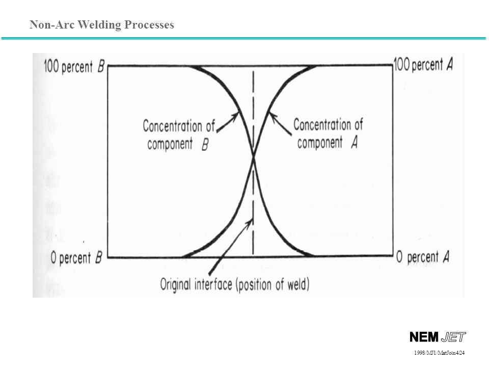
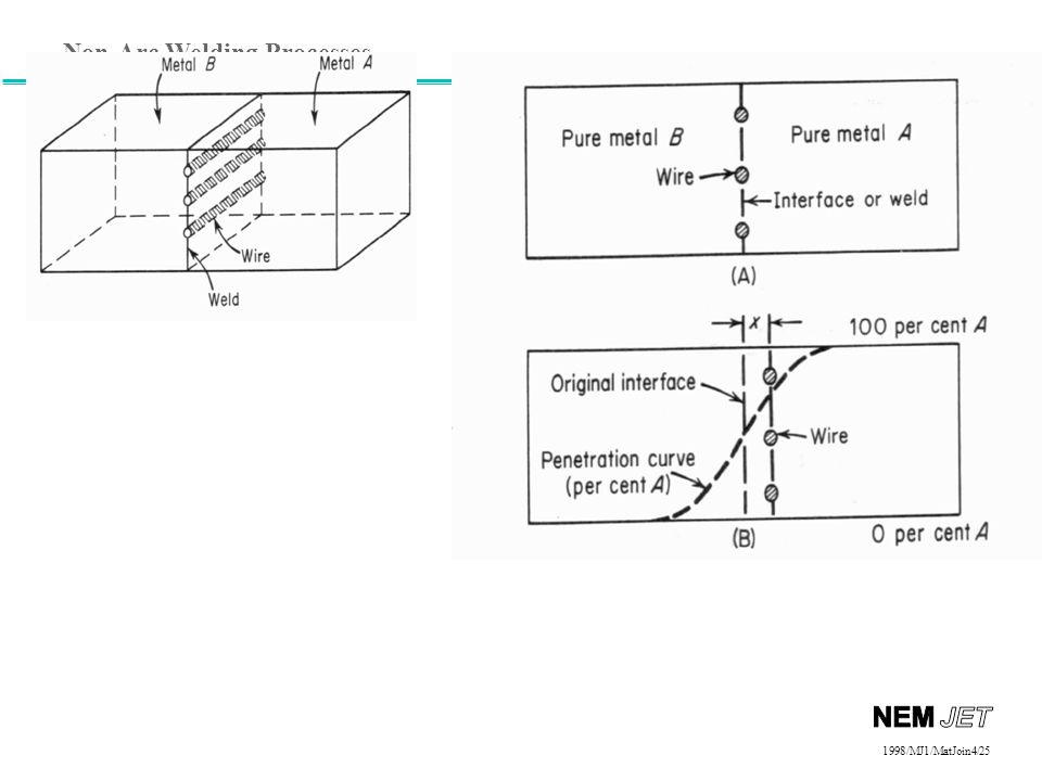
Introduction Non-Arc Welding Processes Resistive heating, chemical reactions, focused light and electrons, sound waves, and friction can also be used to join materials Resistance welding Oxy-Fuel Welding Friction welding (&Solid State) Laser and electron beam welding Brazing and soldering Plastics joining Adhesive bonding Many processes used today do not rely on an electrical arc. Fusion welding (complete melting and mixing of the weld area) as well as solid state welding (no melting of the weld area) can be accomplished by using several different processes, depending on each different situation. Resistance welding, used mostly in the production of automobiles, is a fast and reliable means of joining thin sheets of metal together. The weld is created by first applying pressure on the two parts to be joined. Once the correct amount of pressure is applied, current is passed between the two (or more) overlapped sheets. Resistive heating results in melting and the formation of a “weld nugget.”
 Laser and electron beam welding. Brazing and soldering. Plastics joining. Adhesive bonding. Many processes used today do not rely on an electrical arc. Fusion welding (complete melting and mixing of the weld area) as well as solid state welding (no melting of the weld area) can be accomplished by using several different processes, depending on each different situation. Resistance welding, used mostly in the production of automobiles, is a fast and reliable means of joining thin sheets of metal together. The weld is created by first applying pressure on the two parts to be joined. Once the correct amount of pressure is applied, current is passed between the two (or more) overlapped sheets. Resistive heating results in melting and the formation of a weld nugget.")
4
Resistance Welding Resistance Welding The resistance of metal to the localized flow of current produces heat Process variables Current Time Force Spot and seam welding Resistance spot welding is the most common of the resistance welding processes. It is used extensively in the automotive, appliance, furniture, and aircraft industries to join sheet materials. In this process, water-cooled, copper electrodes are used to clamp the sheets to be welded into place. The force applied to the electrodes insures intimate contact between all the parts in the weld configuration. A current is then passed across the electrodes through the sheets. Spot welding

5
Spot Weld electrode electrode
The contact resistance between the two pieces of sheet metal to be joined is much higher than the bulk resistance of the copper electrodes or of the sheet metal itself. Therefore, the highest resistive heating occurs between the two pieces of sheet metal. As current continues to flow, melting occurs and a weld nugget is formed between the two sheets. On termination of the welding current, the weld cools rapidly under the influence of the chilled electrodes. This causes the nugget to resolidify, joining the two sheets of metal. Resistance spot welding is used extensively because it is a simple, inexpensive, versatile, and forgiving process. It has been shown to be adaptable to some degree of feedback control.

6
Electrodes Truncated cone Dome Pointed
Resistance Welding Electrodes Truncated cone Dome Pointed Electrode tips wear during service, causing nugget size to decrease Zinc-coating on steel alloys with copper electrodes to form brass Copper base materials, divided into classes The basic electrode geometry is usually selected to improve the electrical-thermal-mechanical performance of an electrode. This is generally a geometry in which the cross-sectional area increases rapidly with distance from the workpiece, thereby providing a good heat sink. The diameter of the electrode contact area is also a consideration: too small an area will produce undersized welds with insufficient strength; too large an area will lead to unstable and inconsistent weld growth characteristics. Electrodes must be able to: conduct current to the workpiece, mechanically constrain the workpiece, and conduct heat from the workpiece. Electrode materials must be able to sustain high loads at elevated temperatures, while maintaining adequate thermal and electrical conductivity. A range of copper-based or refractory-based electrode materials are used based on the application. Three groups of electrode materials are outlined below. Within each group, the Resistance Welding Manufacturers Association (RWMA) sorts electrode materials into classes. Group A contains copper-based alloys. Common examples are: Class 1 (99% copper, 1% cadmium; 60 ksi UTS (forged); conductivity 92% IACS) Specifically recommended, because of its high electrical and thermal conductivity, for spot welding aluminum alloys, magnesium alloys, brass and bronze. Class 2 (99.2% copper, 0.8% chromium; 62 ksi UTS (forged), 82% IACS) General purpose electrode material for production spot and seam welding of most materials. Group B contains refractory metals and refractory metal composites. Group C contains specialty materials such as dispersion-strengthened copper.
 sorts electrode materials into classes. Group A contains copper-based alloys. Common examples are: Class 1 (99% copper, 1% cadmium; 60 ksi UTS (forged); conductivity 92% IACS) Specifically recommended, because of its high electrical and thermal conductivity, for spot welding aluminum alloys, magnesium alloys, brass and bronze. Class 2 (99.2% copper, 0.8% chromium; 62 ksi UTS (forged), 82% IACS) General purpose electrode material for production spot and seam welding of most materials. Group B contains refractory metals and refractory metal composites. Group C contains specialty materials such as dispersion-strengthened copper.")
7
Operating Window - Lobe Curve
Resistance Welding Operating Window - Lobe Curve Constant electrode force Acceptable nugget size Time (cycles of current) Nugget too small Expulsion Acceptable-sized weld nuggets can be produced over a range of currents. At the low end of this current range is the minimum nuggets size, which can be found in a resistance welding manual and is based on the diameter of the electrode face. At the upper end of the current range is the expulsion limit. Expulsion is a condition in which the weld nugget grows to a size which cannot be contained by the electrode force; molten metal bursts out of the weld seam. The current range over which an acceptable nugget size is obtained is a measure of the robustness of the welding process. A wide current range indicates that significant variations in the process can occur while maintaining some minimum weld quality. A narrow range, on the other hand, indicates that minor variations in process conditions can result in unacceptable weld quality. The weldability lobe graphically represents the range of acceptable welding currents as a function of welding time. The minimum and expulsion currents are determined for a number of welding times at a particular electrode force. Separate lines are drawn to connect the minimum-weld-size currents and the expulsion currents. The weldability lobe is given as the range of acceptable currents between the two lines. The required current level for making a consistently-sized weld (presumably just below expulsion) is probably the simplest method of defining weldability. This measure of weldability is an indication of the size of welding transformers required to weld the materials of interest. For uncoated steel with a thickness of 0.8-mm (6.1-mm electrode diameter, cycles of welding current) the welding current is 9000 amperes (A). The same sheet with a hot-dipped galvanized coating requires 13,000 A. Current (1000’s of amperes)
 Nugget. too small. Expulsion. Acceptable-sized weld nuggets can be produced over a range of currents. At the low end of this current range is the minimum nuggets size, which can be found in a resistance welding manual and is based on the diameter of the electrode face. At the upper end of the current range is the expulsion limit. Expulsion is a condition in which the weld nugget grows to a size which cannot be contained by the electrode force; molten metal bursts out of the weld seam. The current range over which an acceptable nugget size is obtained is a measure of the robustness of the welding process. A wide current range indicates that significant variations in the process can occur while maintaining some minimum weld quality. A narrow range, on the other hand, indicates that minor variations in process conditions can result in unacceptable weld quality. The weldability lobe graphically represents the range of acceptable welding currents as a function of welding time. The minimum and expulsion currents are determined for a number of welding times at a particular electrode force. Separate lines are drawn to connect the minimum-weld-size currents and the expulsion currents. The weldability lobe is given as the range of acceptable currents between the two lines. The required current level for making a consistently-sized weld (presumably just below expulsion) is probably the simplest method of defining weldability. This measure of weldability is an indication of the size of welding transformers required to weld the materials of interest. For uncoated steel with a thickness of 0.8-mm (6.1-mm electrode diameter, cycles of welding current) the welding current is 9000 amperes (A). The same sheet with a hot-dipped galvanized coating requires 13,000 A. Current (1000’s of amperes)")
8
Resistance seam welding is a variation on resistance spot welding
Resistance seam welding is a variation on resistance spot welding. In this case, the welding electrodes are motor-driven wheels rather than stationary caps. This results in a rolling resistance or seam weld. There are three independent parameters in configuring seam welding machines: power supplies and controls, welding wheel configuration, and sheet configuration.

9
Roll spot weld Overlapping seam weld Continuous seam weld
The major concern with power supplies and control is the frequency with which current is applied to the workpiece. Depending on this frequency and the speed with which the material is being welded, the weld will be either a continuous seam weld, an overlapping seam weld, or a roll spot weld. Overlapping or Continuous Seam welds are typically used to produce continuous gas- or water-tight joints in sheet assemblies, such as automotive gasoline tanks. The process is also used to weld longitudinal seams in structural tubular sections that do not require leak-tight seams. In most applications, two wheel electrodes, or one translating wheel and a stationary mandrel, are used to provide the current and pressure for resistance seam welding.

10
High speed, < 0.1 seconds in automotive spot welds
Resistance Welding Advantages High speed, < 0.1 seconds in automotive spot welds Excellent for sheet metal applications, < ¼-inch No filler metal

11
Process Disadvantages and Limitations
Resistance Welding Process Disadvantages and Limitations Higher equipment costs than arc welding Power line demands Nondestructive testing Low tensile and fatigue strength Not portable Electrode wear Lap joint requires additional metal Several disadvantages are associated with this process. Resistance welding equipment is more expensive than arc welding equipment. The process lacks the portability of arc welding. Although individual spot welding guns may have limited movement on the assembly line, the power source is fixed. Parts to be joined are limited to a thickness of less than 1/4 of an inch due to current requirements. Thicker base materials have a greater ability to dissipate heat away from the weld area. Also, the resistance welding process is limited to overlapping joints, which requires more material than a butt joint. The process can produce unfavorable power line demands, particularly with single-phase as opposed to 3-phase transformers. Short time, high power demands can cause lights to dim and computers to reset if the electrical system in a factory is not properly prepared for the introduction of resistance welding equipment. The lack of a simple, in-process nondestructive testing technique for resistance spot and seam welding is also a limitation. Because resistance welds are produced between overlapping sheets, there can be no visual examination if the finished weld. Also, the time required for ultrasonic inspection of individual spot welds would be unacceptable in a high production environment such as the automotive industry. Spot welds have low tensile and fatigue strength; the notch around the periphery of the nugget between the sheets acts as a stress concentrator. Electrode wear acts to increase the diameter of the electrode face. During production, current values must slowly rise to compensate for the decreased current density, else nugget size drops.

12
Videos Link to the “Resistance Welding Videos from the Video Page on the WE300 Webpage

13
Questions? Turn to the person sitting next to you and discuss (1 min.): If the Lobe Curve represents the welding parameter combinations which produce good welds, why do so many of the automotive spot welds have expulsion? Turn to the person sitting next to you and discuss (1 min.): When spot welds are place too close to one another, some of the current from the second weld shunts thru the first. Why then can overlap seam welds work when the welds are so close that they overlap?
: When spot welds are place too close to one another, some of the current from the second weld shunts thru the first. Why then can overlap seam welds work when the welds are so close that they overlap")
14
Non-Arc Welding Processes
Introduction Non-Arc Welding Processes Resistive heating, chemical reactions, focused light and electrons, sound waves, and friction can also be used to join materials Resistance welding Oxy-Fuel Welding Friction welding (&Solid State) Laser and electron beam welding Brazing and soldering Plastics joining Adhesive bonding
 Laser and electron beam welding. Brazing and soldering. Plastics joining. Adhesive bonding.")
15
Linnert, Welding Metallurgy,
( Oxygen from torch) (Oxygen from Air) Linnert, Welding Metallurgy, AWS, 1994
 (Oxygen from Air) Linnert, Welding Metallurgy, AWS,")
16
Thermite Welding Base Metal Liquid
Power Fe2O3 + 2Al > 2Fe + Al2O3 + heat Base Metal Chemical reactions are also used in joining materials together. Thermite reactions induce extremely high temperatures, add filler metal, and produce a slag. This process is widely employed in the joining of railroad track. The chemical reaction is as follows: metal oxide + aluminum => aluminum oxide + metal + heat Liquid

17
Questions? Turn to the person sitting next to you and discuss (1 min.): The oxy-fuel and that thermit welding are both chemical burning reactions. In the first oxygen is supplied by oxygen gas, in the thermit welding, it is supplied by the iron oxide. Why does this aluminum “burning” in the thermit welding work?

18
Non-Arc Welding Processes
Introduction Non-Arc Welding Processes Resistive heating, chemical reactions, focused light and electrons, sound waves, and friction can also be used to join materials Resistance welding Oxy-Fuel Welding Friction welding (&Solid State) Laser and electron beam welding Brazing and soldering Plastics joining Adhesive bonding Solid state welding includes, but is not limited to, using friction and sound as a means of joining. A friction weld occurs when two pieces are brought together under pressure and rotated very rapidly relative to each other. The heat produced when the two pieces come into contact brings the materials up to a welding temperature just lower than the material’s melting point. The materials become plastic and are welded together by pressure and diffusion.
 Laser and electron beam welding. Brazing and soldering. Plastics joining. Adhesive bonding. Solid state welding includes, but is not limited to, using friction and sound as a means of joining. A friction weld occurs when two pieces are brought together under pressure and rotated very rapidly relative to each other. The heat produced when the two pieces come into contact brings the materials up to a welding temperature just lower than the material’s melting point. The materials become plastic and are welded together by pressure and diffusion.")
19
Solid-State Welding Processes that produce a weld through the application of pressure at a temperature below the melting temperature of the base material; no filler metal is used Friction welding Diffusion welding Ultrasonic welding Explosion welding Solid-state welding is a group of welding processes that produce a weld with the application of pressure at a temperature below the solidus of the base materials. By joining materials in the solid state, many of the difficulties of the fusion processes are avoided. When dissimilar metals are joined, the thermal expansion mismatch between the two materials becomes of less importance since the bonding temperature is decreased in solid state processes. T

20
Friction Welding (FRW)
Friction welding is a process which produces a weld under a compression force. The workpieces are brought into contact and rotated very rapidly to produce heat. Usually one piece is rotated against a stationary piece to produce the heat at the junction. Geometries that have a rotational symmetry are particularly suitable for friction welding. These can include round bars and tubes, as well as bars-sheet and tube-sheet applications. Linear friction welding is used for parts with non-rotational symmetry. In this application, one part is oscillated back and forth against the other. Drawing from Welding Handbook, 8th Edition, Volume 2, American Welding Society. T

21
Friction Welding - Advantages
For correct part geometry, friction welding is faster than most other processes Can join dissimilar materials together Copper to steel or aluminum Easily automated for high volume production Can join plastics Solid-state welding is a group of welding processes that produce a weld with the application of pressure at a temperature below the solidus of the base materials. By joining materials in the solid state, many of the difficulties of the fusion processes are avoided. When dissimilar metals are joined, the thermal expansion mismatch between the two materials becomes of less importance since the bonding temperature is decreased in solid state processes. Friction welding is a process which produces a weld under a compression force. The workpieces are brought into contact. One part is held stationary and the other is rotated rapidly against it to produce heat. The two parts are forced together as rotation is stopped. Hot material and impurities are squeezed from the interface in the form of a flash. The flash can be trimmed off in the machine to produce a smooth surface, which is ready for further processing such as painting. Geometries that have a rotational symmetry are particularly suitable for friction welding. These can include round bars and tubes, as well as bars-sheet and tube-sheet applications. Linear friction welding is used for parts with non-rotational symmetry. In this application, one part is oscillated back and forth against the other. Friction welding requires part geometries with rotational symmetry. The speed of the process,. as well as its ease of automation, promotes high volume production. The joining of dissimilar metals can often be accomplished by the friction process, despite that fact that the metals cannot be joined by conventional fusion processes. For example, copper and steel cannot be joined by arc welding. The two materials are incompatible when melted together. A friction weld between the two metals, however, results in a strong bond. The process is not limited to metals. Indeed, friction welding is a major method for the joining of plastics.

22
Limitations of Friction Welding
Start-up cost is high Parts must be able to rotate about an axis of symmetry Free machining alloys are difficult to weld Non-forgeable materials cannot be friction welded Friction welding requires part geometries with rotational symmetry. The speed of the process, as well as its ease of automation, promotes high volume production. The joining of dissimilar metals can often be accomplished by the friction process, despite that fact that the metals cannot be joined by conventional fusion processes. For example, copper and steel cannot be joined by arc welding because they are incompatible when melted together. A friction weld between the two metals, however, results in a strong bond. The process is not limited to metals. Friction welding is a major method for the joining of plastics. Despite its advantages of speed and range of materials, the friction welding process has its limitations. As has been mentioned, the parts must be able to rotate on an axis of symmetry. Although linear friction welding is an option, the equipment and fixturing is more expensive. Non-forgeable metals cannot be friction welded. These materials tend to crumble upon the application of heat and pressure. Also, free-machining alloys are often difficult to weld. The inclusion content, which promotes chip formation during cutting, leads to difficulties as the parts are spun and forged together.

23
Diffusion Welding Working Principles
1st stage deformation forming interfacial boundary. 2nd stage Grain boundary migration and pore elimination. 3rd stage Volume diffusion and pore elimination. 1st stage deformation and interfacial boundary formation asperities come into contact. 2nd stage grain boundary migration and pore elimination 3rd stage volume diffusion pore elimination Two necessary conditions must be met before a satisfactory diffusion weld can be made. They are: (a) Mechanical intimacy of the faying surfaces. (b) Disruption and dispersion of surface contaminants Stage 1 involves deformation of asperities. This deformation may be temperature and time dependent, similar to creep. Stage 2 includes boundary migration, recrystallization, and pore size reduction. Stage 3 involves bulk diffusion phenomenon including oxide and contaminant desolution, and further pore size reduction.
 Mechanical intimacy of the faying surfaces. (b) Disruption and dispersion of surface contaminants. Stage 1 involves deformation of asperities. This deformation may be temperature and time dependent, similar to creep. Stage 2 includes boundary migration, recrystallization, and pore size reduction. Stage 3 involves bulk diffusion phenomenon including oxide and contaminant desolution, and further pore size reduction.")
27
AWS Welding Handbook

28
Ultrasonic Welding Advantages Limitations Fast Can spot or seam weld
Equipment complex, many variables Only use on small parts More on this below for plastics Ultrasonic welding processes occur when vertical oscillations at frequencies of 10 to 50 kHz are transmitted through polymers and dissipated in a bond line. The parts to be joined are held together under pressure and are subjected to ultrasonic vibrations at right angles to the contact area. The high-frequency stresses produce heat in the material and, if the components are properly designed, this heat can be selectively generated at the joint interface. Heat is generated through a combination of friction and hysteresis. The amplitude of the oscillations can be in the range of 20 to 60 microns, significantly less than the amplitude of movement in friction welding. The sound energy oscillations are generated by the ultrasonic welder and transferred to the parts being welded by what is called a horn. The design of the horn as well as the anvil or base of the ultrasonic welder is critical to the success or failure of the process as it must transmit a specific wavelength of sound into a specific joint geometry. Ultrasonic welding equipment is typically costly, which makes it impractical for short production runs. Ultrasonic welding is probably the most commonly used method to join thermoplastics. It is fast (a few seconds or less), clean, and usually produces welds that are relatively free of flash. In addition, ultrasonic welding is relatively easy to automate since fixtures can act as anvils and the horn can be applied outside the part to produce a weld on an inside surface. Items commonly made by ultrasonic welding include, dashboard assemblies for automobiles, and 3-inch computer disks. Note that most of these items are small; size is a limitation of the process.
, clean, and usually produces welds that are relatively free of flash. In addition, ultrasonic welding is relatively easy to automate since fixtures can act as anvils and the horn can be applied outside the part to produce a weld on an inside surface. Items commonly made by ultrasonic welding include, dashboard assemblies for automobiles, and 3-inch computer disks. Note that most of these items are small; size is a limitation of the process.")
29
Principles of Explosion Welding
Detonator Welding arrangement consists of three components - Base component Prime component Explosive. Base component remains stationary, supported by anvil. Explosive prime component Base component Component arrangement for explosion welding In explosive welding, the prime component is propelled toward the base component by an explosive charge (see figure above). The base component is supported on an anvil. The explosion deforms the prime component and accelerates it across the standoff distance between the components.
. The base component is supported on an anvil. The explosion deforms the prime component and accelerates it across the standoff distance between the components.")
30
Principles of Explosion Welding
Prime component is placed either parallel or at an angle to the base. Explosive is distributed over top surface of prime component. Upon detonation, prime component collides with base component to complete welding. Detonation Prime component Weld Jet The collision between the components produces an interaction that produces local melting, vaporization, and possibly plasma formation. Most of the liquid and vapor is expelled from the joint by a strong jet action at the interaction point. The resulting weld has a wavy appearance. Base component Action between components during explosion welding.

31
Linnert, Welding Metallurgy,
AWS, 1994

32
Questions? Turn to the person sitting next to you and discuss (1 min.): In friction welding, the outer part of the bar is moving faster and will therefore have more heating than the exact center of the bar. What might you do to “even out” the heating across the entire interface?

33
Do Special Project Homework on Solid State Welding

Similar presentations


 Interstitials Austenitic Nitrogen Strengthened Austenitic Martensitic Ferritic Precipitation Hardened.>")

>")
