Download presentation
Presentation is loading. Please wait.

1
CAD-CAM IN FPD

3
TECHNOLOGICAL TRENDS IN DENTISTRY
Information systems Treatment systems

4
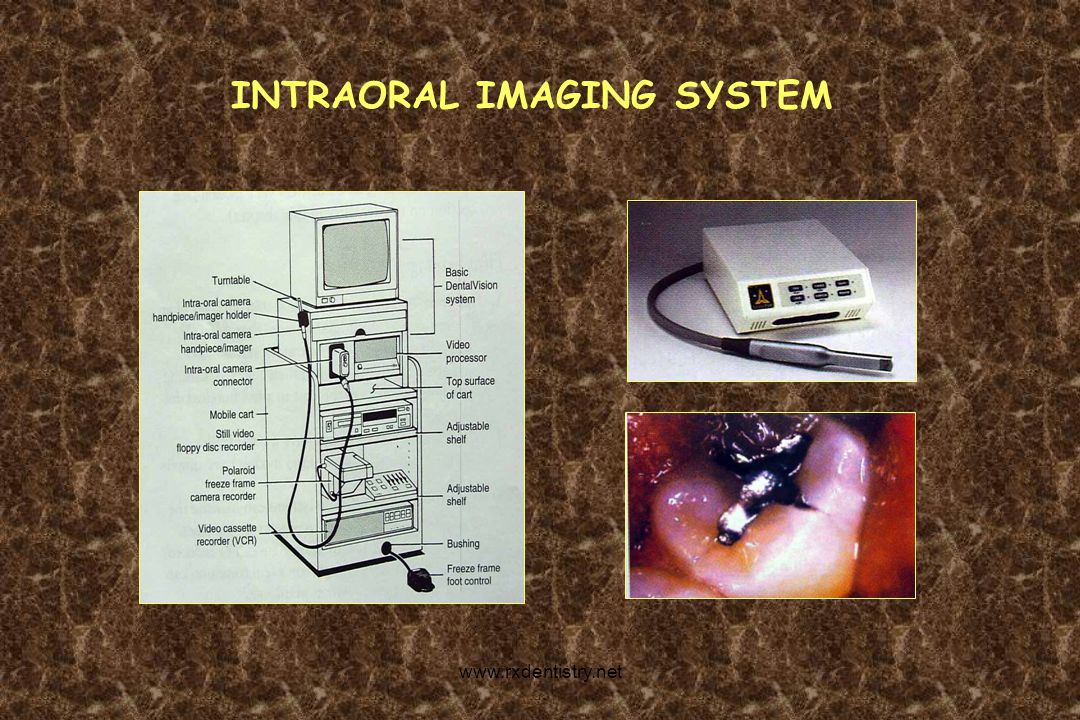
INTRAORAL IMAGING SYSTEM
5
COMPUTER IMAGING SYSTEM

6
CAD-CAM SYSTEM

7
DIGITAL RADIOGRAPHIC SYSTEM

8
COMPUTERIZED PERIODONTAL PROBE

9
RADIOGRAPHIC IMAGE PROCESSING SYSTEM

10
TREATMENT SYSTEMS Abrasive system Laser system

11
CAD-CAM SYSTEM Acronym for computer aided designing and computer aided milling or machining.
12
BRIEF HISTORY Increasing demand Restoration at a single appointment
Development- began in 1970’s with Duret in France. French system - in 1983 by Dr.Francois Duret

13
Mormann 1985 in Zurich, Switzerland
On September 19, 1985, the first ceramic inlay was produced- at the dental Institute of the University of Zurich. Mormann 1985 in Zurich, Switzerland

16
FUNDAMENTAL PRINCIPLES OF CAD/CAM SYSTEM
CSD CAD CAM

17
ADVANTAGES One visit restoration Time saving Improved esthetics
Good morphology Improved crown fit

18
Less fracture due to single homogenous block
Excellent polish Less fracture due to single homogenous block Wear hardness similar to enamel (Craig 1980) Minimize cross infection Good patient acceptance
 Minimize cross infection. Good patient acceptance.")
19
DISADVANTAGES Need for costly equipment Need for extended training
Technique sensitive Inability to image in a wet environment

20
MACHINABLE CERAMIC MATERIALS
Dicor MGC Vita Mark II Inceram Alumina Inceram Spinell Inceram Zirconia Pro-Cad Procera Allceram

21
MACHINABLE CERAMIC FRACTURAL STRENGTH
Dicor MGC 229MPa Vita Mark II 122MPa Inceram Alumina 500MPa Inceram Zirconia 700MPa Inceram Spinell 350MPa

22
CERAMIC BLOCKS Available in wide range of shades and sizes
More homogenous Less porous Mounted on a metal stub

23
Effects of surface finish and fatigue testing on the fracture strength of CAD-CAM and pressed – ceramic crown (Hickel - JPD 1999) Purpose To determine the fracture strength of various all ceramic crowns with and without cyclic loading.

24
Material & Method Machinable ceramic material, Vita Mark II and ProCAD and conventional heat-pressed IPS – Empress crowns were fabricated, with either a polished or an oven – glazed surface finish. Cyclic loading that simulated oral conditions were performed on half of each group.

25
Conclusion The Cerec Pro-CAD crowns had significantly greater strength than the Vita Mark II crowns, better resistance to cyclic loading and lower failure probability than laboratory fabricated IPS empress crowns.

26
Cyclic loading significantly reduced the strength of all-ceramic crowns, but had less effect on cerec crowns than on the IPS Empress crowns. Oven-glazing of ProCAD crowns resulted in significantly higher strength and higher resistance to cyclic loading than surface polishing.

27
An upto 5 year Clinical Evaluation of posterior In-ceram CAD/CAM core crowns (Mormann – Int. J Prosthodont 2002) Evaluated the clinical performance of posterior CAD-CAM generated In-ceram alumina and In-ceram spinelll core crowns using the corec 2 CAD-CAM system and after 5 years of service concluded that the clinical quality of CAD-CAM generated In-ceram Alumina and In-ceram Spinell posterior crowns was excellent

28
Computer generated restoration design Polishing and cementation
CLINICAL PROCEDURE Preparation Design Optical Impression Computer generated restoration design Milling Polishing and cementation

29
PREPARATION DESIGN

30
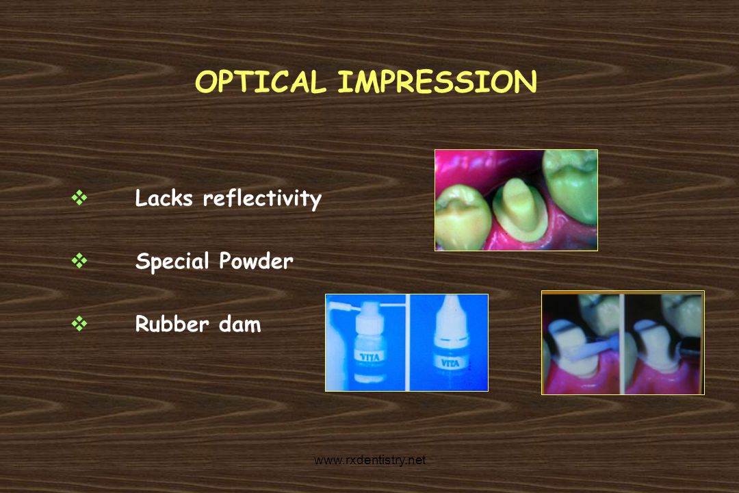
OPTICAL IMPRESSION Lacks reflectivity Special Powder Rubber dam
32
COMPUTER GENERATED RESTORATION DESIGN
Restoration is designed Operator moves the cursor 3-D image Design phase – 2 – 8 min.

33
MILLING Computer selects Block is inserted Milling device is activated
Three axis of rotation cutting machine

35
PROCESSING TIME Process Step Coping Bridge framework Scanning
Approx. 10min Approx. 20min Designing Approx. 2 min Approx. 6 min Milling Approx. 15min Approx. 50min

36
POLISHING Rough ceramic surfaces are smoothed with clean white stones
Polished with - Rubber wheel of fine grit - Diamond impregnated wheels & points

37
CEMENTATION Composite resin cement Zinc phosphate Glass ionomer
Ceramic restoration that have been etched internally and bonded with a composite resin cement are 50% stronger than similar restoration cemented with zinc phosphate cement (Ludwig 1994)
")
38
Four preparation types were used
Effects of Preparation and Luting system on All-ceramic computer generated crowns (Mormann – Int. J Prosthodont 1998) Examined the effect of inside crown form on fracture strength of cemented and bonded crowns. Four preparation types were used
 Examined the effect of inside crown form on fracture strength of cemented and bonded crowns. Four preparation types were used.")
39
Machined crown were placed on abutments
a. Without any media as control group b. Cemented with zinc phosphate c. Bonded And were loaded until fracture

40
RESULTS Zinc phosphate cemented crowns showed significant increase of fracture load values compared to uncemented control crowns. Fracture load values of bonded crowns were significantly higher than those for cemented crowns. Bonded crowns with thick occlusal dimension showed the highest fracture load values.

41
He concluded that bonded all ceramic CAD-CAM crowns with defect oriented inside morphology and increased occlusal dimension showed high fracture load values.

42
PROCERA CAD/CAM SYSTEM TITAN CAD/CAM SYSTEM CELAY CAD/CAM SYSTEM
CEREC CAD/CAM SYSTEM PROCERA CAD/CAM SYSTEM TITAN CAD/CAM SYSTEM CELAY CAD/CAM SYSTEM CICERO CAD/CAM SYSTEM LAVA CAD/CAM SYSTEM

43
CEREC SYSTEM Chair side economical reconstruction of esthetic ceramic.
- Cerec 3 – Feb’ 2000

44
CEREC CAD-CAM SYSTEM Limitation Cannot mill the occlusal surface
Only inlays and onlays

45
CEREC – 2 CAD-CAM SYSTEM Milling of occlusal surface possible
Inlays, Onlays, veneers and crowns Milling time approx. 10min

46
The grinding precision of the cerec-2 is 2
The grinding precision of the cerec-2 is 2.4 times higher than cerec system (Mormann 1997)
")
47
CEREC – 3 CAD-CAM SYSTEM Advanced version Technical improvements
Designing and grinding- less time (27%) Grinding unit – 2 cutters
 Grinding unit – 2 cutters.")
49
Marginal and Internal Fit of Cerec 3 Cad/CAM All Ceramic Crowns (Kojima – Int. J Prosthodont 2003)
Examined the effect of the occlusal convergence angle of the abutment and the computer luting space setting on the marginal and internal fit of cerec 3 CAD-CAM all ceramic crowns. Mandibular second premolar all ceramic crowns were fabricated for nine different conditions using cerec-3 CAD-CAM system

50
Occlusal convergence angle of 4,8 and 12°
Luting space settings of 10, 30 and 50µm.

51
Total Oclusal Convergence
Luting Space 10µm 30µm 50µm Marginal Gap 4° 8° 12° 108 95 66 53 61 67 55 Internal Gap 119 135 136 116 132 141 162 146

52
He concluded that when the luting space was set to 30µm, crowns with a good fit could be fabricated with the cerec 3 system, regardless of the occlusal convergence angle of the abutment.

53
PROCERA CAD-CAM SYSTEM
Nobel Biocare Initially introduced in 1985 Titanium copings Utilizing the latest scanning, CAD-CAM and manufacturing technologies Procera Allceram crown in 1991 Procera Allceram bridge in 1999

54
TITANIUM CROWN AND FPDS SUBSTRUCTURE
Reading Milling Spark erosion

55
READING The prepared die is attached
Contact probe registers the surface

56
MILLING The probe tip of the reader and the tip of the milling tool are of same size. The graphite electrode is milled

57
SPARK EROSION Used in dentistry since 1982
Graphite electrode is fitted Removes the metal by electricity in the form of controlled sparks to fabricate copings.

59
PROCERA ALL CERAM CROWN
Composed of densely sintered, high purity aluminium oxide coping that is combined with low-fusing Allceram veneering porcelain.

60
Preparation of the tooth
Computer assisted design Manufacture of the coping Addition of the veneering porcelain

61
PREPARATION OF THE TEETH
Recommendations for the preparation Depth orientation grooves 1.5mm Incisal reduction – 2.0mm Axial reduction – 1.5mm

62
Rounded, smooth contours and lack of line angles

63
Impression is made Die is fabricated Articulated

64
COMPUTER ASSISTED DESIGN
Die is oriented vertically Tip of the scanner probe is brought in contact As the platform rotates, one data point is collected at every degree around the 360° circumference of the die.

65
More than 50,000 data points are registered
Scanning takes 3min More than 50,000 data points are registered Verified on the computer screen for completeness Vertical gap

66
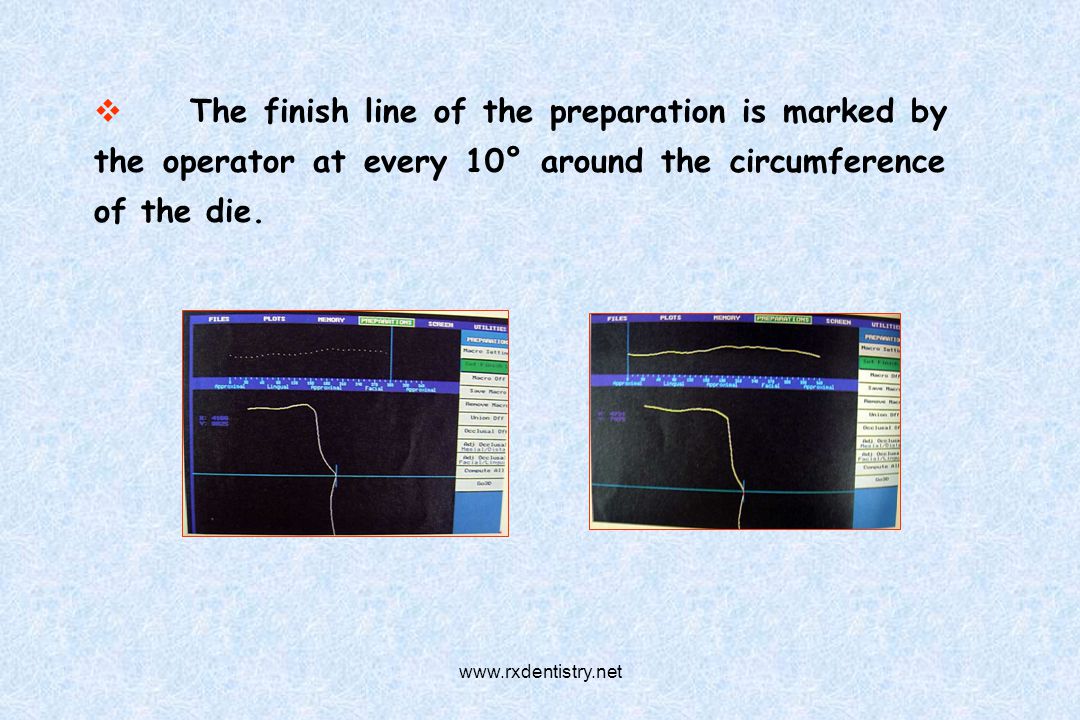
The finish line of the preparation is marked by the operator at every 10° around the circumference of the die.
67
Coping design is selected
Merged with the die and its finish line.

68
MANUFACTURE OF THE COPING
When the design of the coping is finalized, it is saved and transferred through a modem communication link to Procera Stanvik AB in Stockholm Sweden, where the coping is fabricated.

69
ADDITION OF THE VENEER PORCELAIN
The coping is sent by mail to the dental laboratory where the ceramist finalizes the restoration by addition of Allceram veneering porcelain to create the appropriate anatomic form and esthetic qualities.

71
Titanium copings veneered with Procera Ceramics : A longitudinal clinical study (Nilson - Int.J Prosthodont 1994) In 1989, 47 titanium copings veneered with a low fusing ceramic were fabricated for 24 patients. 44 crowns could be examined after a period varying between 26 and 30 months.

72
CDA ratings for surface and color changed markedly from the Excellent to the acceptable level.
For marginal integrity it was recorded as satisfactory for all crowns and a large majority were rated excellent.

73
A comparison of the Fit of Spark – Eroded Titanium Copings and cast gold alloy copings (Wickens - Int. J. Prosthodont 1994) Compared the fit of spark eroded titanium and cast gold alloy copings and showed that the overall fit of titanium copings was comparable to that of gold copings. In marginal areas, the space between die and coping was found to be larger for spark eroded than cast copings.

74
TITAN CAD-CAM SYSTEM Production of metal copings for porcelain fused to metal restorations Digitizing Processing Milling

75
Conventional Technique
Preparation Impression Die Waxing Investing Casting Digitizing Processing Milling Conventional Technique CAD/CAM system

76
DIGITIZING Die is fabricated Mounted on the digitizer
Data are recorded Short circuited

77
Divided into 200µm x 200µm squares
Digitized at least twice The finish line and the adjacent 1mm area are recorded first

78
PROCESSING The main parameters for the copings are then determined – The gap between the coping and the die - The width and shape of the coping

79
MILLING Uses titanium alloy dummies of various widths in the form of disks or blocks Milling device consist of two major units - A rotatory drilling element with interchangeable bores - A mobile platform to which the dummy is fixed

80
Rough milling inside the coping
Three steps Rough milling inside the coping Fine milling inside the coping Rough external milling

81
MULTIPLE UNIT RESTORATION
Steps same as for the single unit restoration It uses master cast made from a multiple unit impression Master cast allows the computation of each individual tooth and of the corresponding residual ridge

82
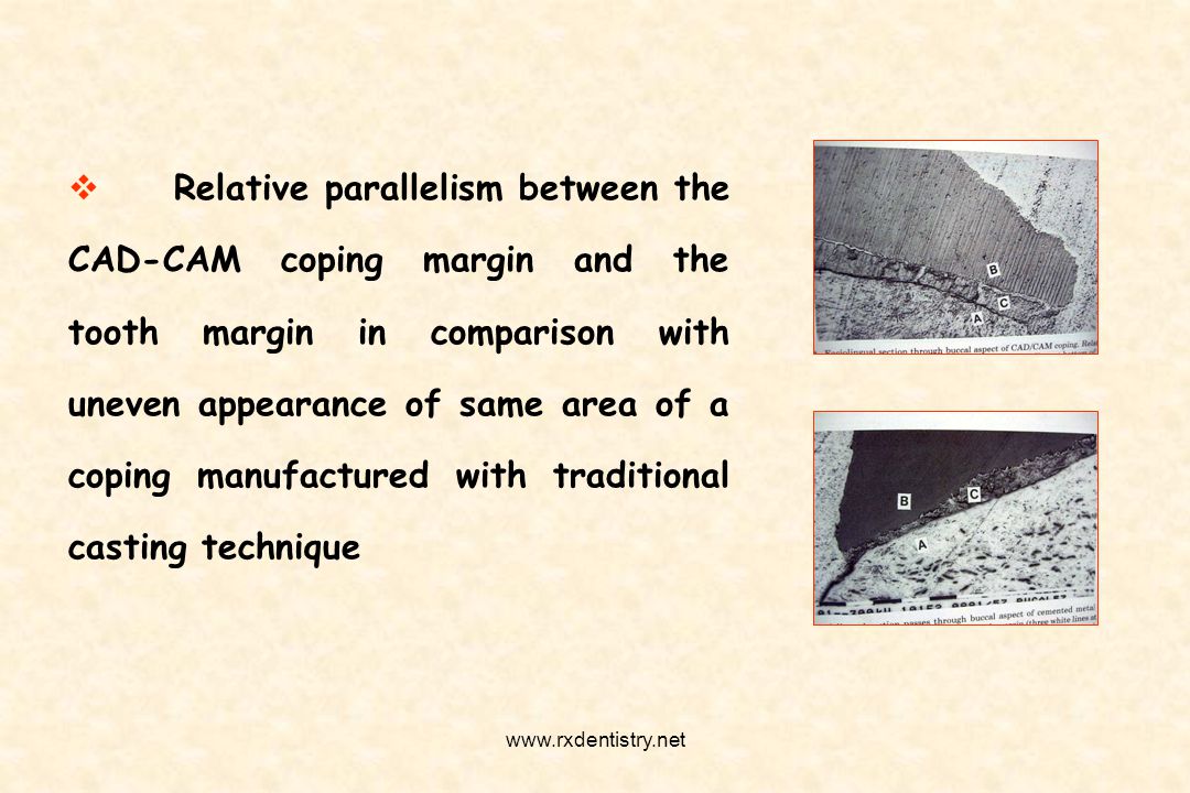
Relative parallelism between the CAD-CAM coping margin and the tooth margin in comparison with uneven appearance of same area of a coping manufactured with traditional casting technique
83
CELAY CAD-CAM SYSTEM Introduced in 1992 by Mikrona Technologies, Switzerland Inlays, onlays, crowns and bridge framework Not a true CAD-CAM system Many features in common

84
A light cured composite replica Either directly or indirectly
Replica is mounted Scanning tools used to trace Milling tools removes ceramic

85
Bulk reduction by rough diamond milling disc
Fine milling disc Contouring by diamond point Milling time 40mins – three unit bridge

87
CICERO CAD-CAM SYSTEM Computer integrated crown reconstruction
First technical concept- by Denisson et al in 1999 Crowns with different ceramic layers such as high alumina core, dentinal and incisal porcelain for maximal strength and enhanced esthetic.

88
Preparation of Scan Model Design of crown layer build-up
STEPS Preparation of Scan Model Optical Scanning Design Occlusion Design of crown layer build-up Production process

89
PREPARATION OF THE SCAN MODEL
Model is marked with black/white contrast

90
OPTICAL SCANNING Obtained by laser scanning of the cast
Upto 1,00,000 surface points are recorded per minute

91
DESIGN Appropriate tooth selected
Mesial and distal contact are outlined The margin line of new crown is adjusted

92
OCCLUSION The new crown is superimposed on the opposing teeth to check for occlusion

93
DESIGN OF CROWN LAYER BUILD-UP
The interior and exterior tooth surfaces are designed and interface surfaces between cement and ceramic core and between dentin and incisal porcelain are defined. Thickness of the ceramic core of 0.7mm Ceramic core – die cement thickness of 0.02mm is adjusted.

94
PRODUCTION PROCESS Refractory block is fitted
Negative of the inside surface of the crown is milled

95
- Diamond cylinder of 5.3mm dia - Diamond rounded disk of 09.3mm dia
Cutting tools used - Diamond cylinder of 5.3mm dia - Diamond rounded disk of 09.3mm dia - Diamond pointed tool of 0.9mm dia Automatically exchanged

96
High strength aluminium oxide based ceramic is applied and sintered
Ceramic is grounded to calculated oversize to compensate the shrinkage that will occur during the final sintering

97
Dental porcelain applied and fired
After firing block is placed on milling machine and interface between dentinal and incisal porcelain is milled

98
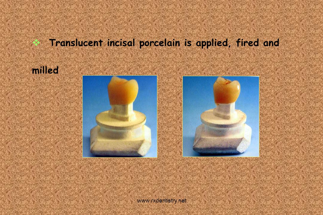
Translucent incisal porcelain is applied, fired and milled
99
LAVA CAD-CAM SYSTEM Produce high strength all ceramic crowns and FPD’s
Uses yttrium tetragonal zirconia polycrystals (Y-TZP) based material Introduced as a hip replacement material in early 1990’s High fractured strength 900 – 1200MPa and biocompatibility
 based material. Introduced as a hip replacement material in early 1990’s. High fractured strength 900 – 1200MPa and biocompatibility.")
100
Special scanner (Lava Scan) Computerized milling machine (Lava Form)
A sintering Oven (Lava Therm) CAD-CAM software technology
 CAD-CAM software technology.")
101
Saw cut working cast is mounted on the scanner
STEPS IN FABRICATION Saw cut working cast is mounted on the scanner The configuration of the tooth preparation are scanned Scanning process takes - Crown – Approx.5min - 3 unit FPD – Approx.12min

102
- Crown coping – Approx.35min - 3 Unit FPD – Approx.75min
Produces an enlarged framework to compensate shrinkage during sintering process. Average milling time - Crown coping – Approx.35min - 3 Unit FPD – Approx.75min

103
The framework is sintered in the Lava Therm
Pre programmed to run for 8hrs, including the heating and cooling phases. The sintered framework is then veneered

106
To conclude, Computer graphics and CAD-CAM have revolutionized dentistry. It is now possible to provide equivalent of a cast restoration in a single appointment

107
BIBLIOGRAPHY Philips Science of Dental Material, - ANUSAVICE
Art & Sciences of Operative Dentistry- STURDEVANT’S Dental Clinics of North America – Fixed prosthodontics Fundamentals of Fixed prosthodontics – SHILLINGBURG Contemporary fixed prosthodontics – ROSENSTEIL Restorative dental material – CRAIG

108
Thank you Thank you

Similar presentations


 placement>")


>")


