Download presentation
Presentation is loading. Please wait.

1
Task 2: Define digital and analogue signals Describe how digital and analogue signals store information Describe the process of: a) three bit ADC circuit and; b) three bit DAC circuit Give example(s) of an application of both ADC and DAC and explain why the conversion is required and also discuss the advantages/disadvantages of different techniques (A/M/E)
 three bit ADC circuit and; b) three bit DAC circuit. Give example(s) of an application of both ADC and DAC and explain why the conversion is required and also discuss the advantages/disadvantages of different techniques (A/M/E)")
2
Analogue and Digital

3
Analogue and Digital Analogue means ‘being able to have a continuous value that can be expressed by a decimal number’. Digital means that there are just two states, ‘0’ and ‘1’, but these can be used to express binary numbers

4
How the information is coded in analogue and digital signals
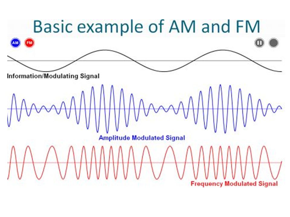
The information in an analogue signal could be coded as: A changing timing of the waveform (frequency modulation) A changing voltage level (amplitude modulation)
 A changing voltage level (amplitude modulation)")
6
How the information is coded in analogue and digital signals
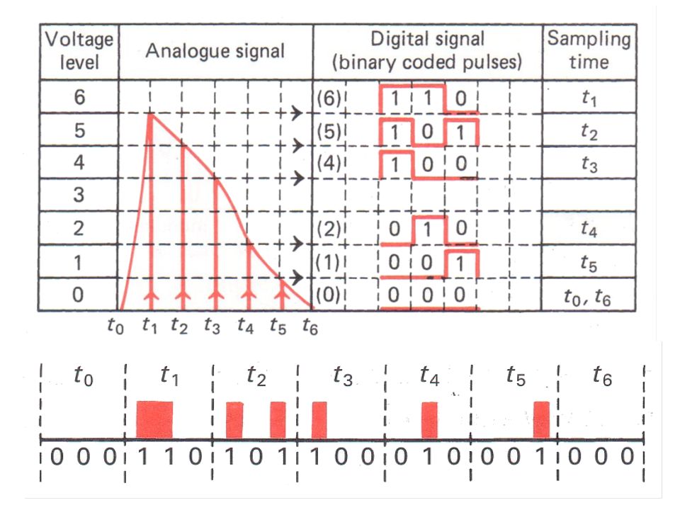
The information in a digital signal could be coded as multi-bit numbers (each bit is a two-state). The bit-rate is what determines the quality of the signal.
. The bit-rate is what determines the quality of the signal.")
8
ADC – Analogue to Digital Conversion “Three-bit ADC Circuit”

9
ADC – Analogue to Digital Conversion
Three-bit ADC Circuit The binary counter counts up as long as it is receiving pulses from the AND gate. The binary counter also makes the voltage (V1) from the ramp generator increase in steps. When V1 = V2 then the comparator shuts off the AND gate and this stops the counter so you can read the 3-bit binary number which is equal to the value of V2.
 from the ramp generator increase in steps. When V1 = V2 then the comparator shuts off the AND gate and this stops the counter so you can read the 3-bit binary number which is equal to the value of V2.")
10
DAC – Digital to Analogue Conversion
Three-bit DAC Circuit

11
DAC – Digital to Analogue Conversion
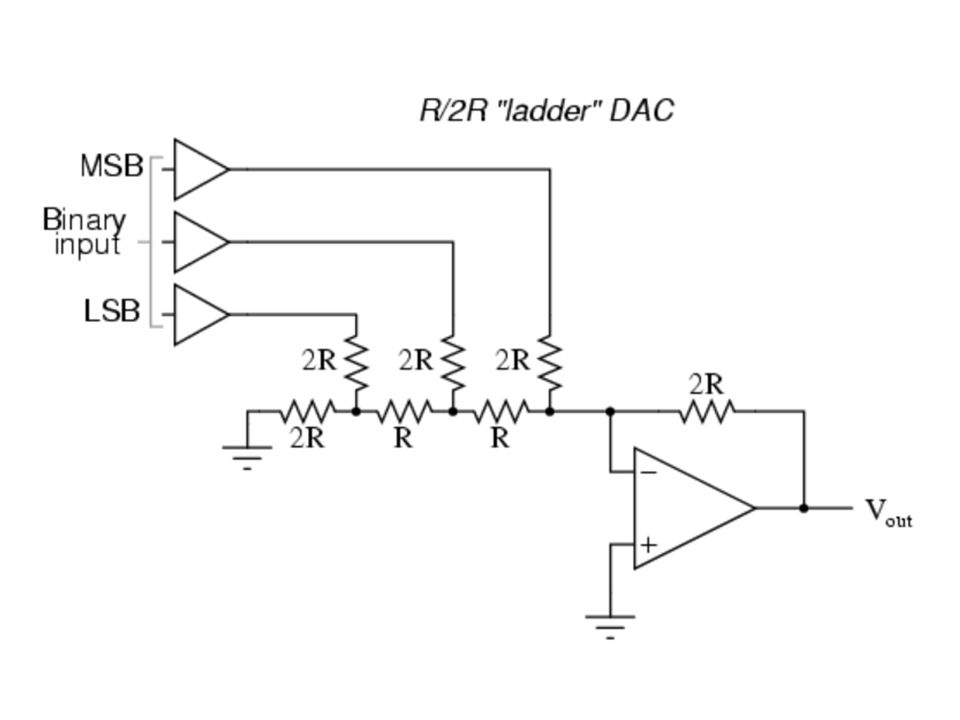
Three-bit DAC Circuit Three-bit binary number (e.g. 101) can be set using the switches. The op-amp behaves as a summing amplifier. The three inputs to the op-amp is added up and give an output voltage that is the correct analogue value of the input (e.g. 101 = 5) The resistor values determine the ‘weight’ of each input.
 can be set using the switches. The op-amp behaves as a summing amplifier. The three inputs to the op-amp is added up and give an output voltage that is the correct analogue value of the input (e.g. 101 = 5) The resistor values determine the ‘weight’ of each input.")
12
Practical Applications of ADC and DAC

14
ADC (Analogue to Digital Conversion)
Example: Recording an audio signal onto a CD An audio signal (analogue) is sampled at a high frequency then quantized so the sampled values can be expressed as a binary number (digital). The digital signal is stored on a CD.
 is sampled at a high frequency then quantized so the sampled values can be expressed as a binary number (digital). The digital signal is stored on a CD.")
17
3-Bit ADC Circuit

18
Ramp-compare ADC

19
DAC (Digital to Analogue Conversion)
Example: An image projector A picture file from a computer (digital input) is converted into an actual image on a screen (analogue output) by an image projector. DAC can be done by using a summing amplifier and a resistor ladder.
 is converted into an actual image on a screen (analogue output) by an image projector. DAC can be done by using a summing amplifier and a resistor ladder.")
22
Resistor Ladder

23
Other practical applications of ADC
Digital voltmeter – measures continuous voltage signals (analogue) then displays them on an LCD in numerical form (digital) Touch screen – senses the position of a finger (analogue) then digitise the signal so that the microprocessor can process the data recognise the coordinate.
 then displays them on an LCD in numerical form (digital) Touch screen – senses the position of a finger (analogue) then digitise the signal so that the microprocessor can process the data recognise the coordinate.")
24
Other practical applications of ADC
Digital camera – the image (analogue) is received through the lens then converted into a picture file (digital). The picture file stores the binary values for the pixels so it can be displayed on a computer screen later.
 is received through the lens then converted into a picture file (digital). The picture file stores the binary values for the pixels so it can be displayed on a computer screen later.")
25
ADC Types Ramp-compare ADC Flash ADC Successive approximation ADC
Integrating ADC Sigma-delta ADC

Similar presentations


>")
 And>")


 Interfacing a microprocessor-based system.>")
 is a device that converts continuous signals to discrete.>")
 Conversion An overview of A/D techniques.>")


>")
 A device that converts continuously varying analog signals from instruments and sensors that monitor conditions,>")


 and provide an output signal when one is bigger than the other are.>")


