Download presentation
Presentation is loading. Please wait.

2
Circuit building blocks that compare the strength of two signals (usually Volts) and provide an output signal when one is bigger than the other are known as comparators. The two inputs of an op-amp make it ideal for comparing two analogue voltages. An input voltage is compared with a reference voltage with V out saturating + ve or – ve depending on the difference between V in and V ref Typical applications include switching circuit in thermostats, light operated switches, ADC and DAC applications

3
Vref Vin

4
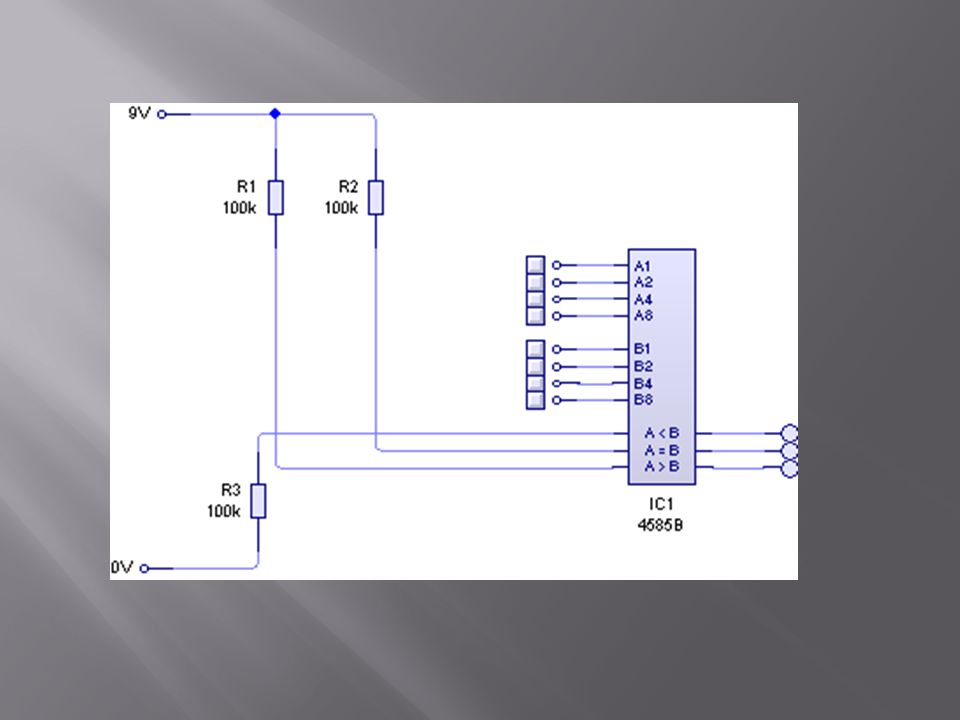
An op-amp can be used as an analogue comparator, as seen previously Magnitude comparators are digital comparators which are used to determine if two binary numbers are equal or which has the greater magnitude Typically TTL or CMOS IC’s can make fully decoded decisions about two 4-bit binary words

6
Analogue to Digital Conversions (ADC) and Digital to Analogue conversions (DAC) Computers work on digital references, the natural world generally works on analogue Temperature, pressure, wind speed, for example, require conversion from analogue to digital if to be processed in a microprocessor. Likewise, before a computer operating a system such as a plotter or model car set, it will need to convert its digital signals to analogue. An ADC will typically operate an input and a DAC as an output. An ADC is referred to as an encoder and a DAC as a decoder Real world eventsADCComputer system DACReal world events

7
Principles of DAC Suppose that the input to a DAC is a 4-bit word. The DAC converts this to a DC voltage ranging from 0V for binary 0000 to 2.25V for binary 1111 A change of one bit in the binary information is equivalent to a change of 0.15V in the output information. e.g. if the input information is 0100 (2), the output information is 4 x 0.15 = 0.6V A 4-bit binary word can provide 16 binary inputs, as shown. Binary inputAnalogu e output DCBAVolts 00000 00010.15 00100.30 00110.45 01000.60 01010.75 01100.90 01111.05 10001.2 10011.35 10101.50 10111.65 11001.95 11102.10 11112.25
, the output information is 4 x 0.15 = 0.6V A 4-bit binary word can provide 16 binary inputs, as shown. Binary inputAnalogu e output DCBAVolts")
8
Principles of ADC The truth table for a 4-bit ADC is the reverse of that for a 4-bit DAC So an analogue input voltage ranging from 0 to 2.25V is converted into a digital output ranging from 0000 to 1111 e.g. an input voltage of 1.8V is converted into a digital output of 1100. Most ADC’s are made up of a comparator and digital logic circuits Typical ADC’s are the single ramp and counter, the dual ramp and counter and the successive approximation ADC

9
Single Ramp ADC

10
8421 00000 00011 00102 00113 01004 01015 01106 01117 10008 10019 101010 101111 110012 110113 111014 111115 The output of a binary counter is connected to a DAC. This produces a ramp wave. A comparator is used to compare the ramp with the signal to be converted. When the comparator changes state, the binary data is is latched. In this way the analogue input is converted to binary numbers. The diagram below shows a 4 bit ADC. 8, 12 and 16 bit converters are more common

11
INPU T OUTPU T RSQQ Start up001/0 indeterminate Set switch pushed 0110set Reset switch pushed 1001reset Disallowed state 1100 1111Stable

Similar presentations


>")


 And>")


 Interfacing a microprocessor-based system.>")


>")
 A device that converts continuously varying analog signals from instruments and sensors that monitor conditions,>")


