Download presentation
Presentation is loading. Please wait.

1
After completing this lesson you will be able to explain the basic principles, operation and function of drum & disc brakes. You will be capable of troubleshooting, diagnosing and repairing drum & disc brake systems.

2
Principles affecting stopping distance Energy Friction Heat dissipation Vehicle weight Speed Weight transfer

3
Energy is Ability to do work Cannot be created or destroyed Can be changed from one form to another Kinetic energy is energy in motion Based on velocity (speed) and mass (weight)
 and mass (weight)")
4
Friction is Resistance to motion Sources of friction Brake system components Road surface and tires

5
The Relationship of weight and speed At any given speed - 4,000 lb vehicle creates twice as much kinetic energy as 2,000 lb vehicle - double amount of heat needs to be dissipated Doubling vehicle speed requires 4 times more braking effort - 4 times more heat energy Doubling weight and speed requires 8 times as much heat to be transferred

6
Weight transfer Requires more braking on front wheels Uses special valve in hydraulic circuit to reduce pressure to rear wheels under certain conditions

7
Stopping distance Controlled by Driver reaction time Vehicle weight and speed Brake system efficiency

8
A liquid under confinement can be used to Transmit pressure Increase or decrease force Transmit motion Liquids cannot be compressed

9
Basic formula is used to determine forces and pressure Force = pressure X area Pressure = force area

10
Liquids can transmit force Liquids can increase force Liquids can decrease force

11
Pascal's law states that when there is an increase in pressure at any point in a confined fluid, there is an equal increase at every other point in the container.

12
The ability of fluid to transfer force through hydraulic pressure is the basis for all modern automotive braking systems

13
Hydraulic Principles Applied to the Vehicle’s Braking System How it works Force is applied to foot pedal Master cylinder piston forces column of fluid to move Fluid cannot be compressed Pressure created by return spring resistance at first then by contact of shoes to drums is equal in all lines and in all wheel cylinders Wheel cylinders’ pistons move outward to force brake shoes against drums

14
Brake Fluid A specially blended liquid that transmits hydraulic pressure from master cylinder to wheel cylinder and/or calipers

15
DOT (Department Of Transportation) 3, 4 or 5 Ratings relate to wet and dry boiling points DOT 3 & 4 are glycol based fluids Super DOT 4 is glycol ether and borate ester based fluids DOT 5 is silicone based fluid Color purple/blue
 3, 4 or 5 Ratings relate to wet and dry boiling points DOT 3 & 4 are glycol based fluids Super DOT 4 is glycol ether and borate ester based fluids DOT 5 is silicone based fluid Color purple/blue")
16
OEMs recommend only one type for their system Note: Almost all ABS systems require DOT 3 DOT 3 and 4 are actively hygroscopic (takes on water) The higher the DOT rating the higher the boiling point/temperature range Moisture will accumulate Reduces boiling point Increases corrosion in system Reduces lubricity of fluid
 The higher the DOT rating the higher the boiling point/temperature range Moisture will accumulate Reduces boiling point Increases corrosion in system Reduces lubricity of fluid")
17
Brake Fluid Viscosity: must flow freely at all temperatures High boiling point: must remain liquid at highest operating temperatures Non-corrosive: must not attack metal or rubber parts

18
Brake Fluid Water tolerance: must be able to absorb and retain moisture that collects in system Lubricating ability: must lubricate pistons and cups to reduce wear and internal friction Low freezing point: must not freeze even at lowest operating temperature

19
Changing Brake Fluid A good practice is to flush system when brake repairs are made Most manufacturers recommend periodic changes (usually every 1 to 2 years) Contamination is indicated by Discolored fluid Corroded parts Soft or swollen rubber parts
 Contamination is indicated by Discolored fluid Corroded parts Soft or swollen rubber parts")
20
Changing Brake Fluid Flush with clean brake fluid Once fluid has been poured from the can it is considered contaminated When bleeding catch bled fluid in a container but do not use it to refill master cylinder

21
Storing Brake Fluid Keep brake fluid clean There should not be any foreign material in fluid Do not get any petroleum product in fluid such as P/S fluid, engine oil, or ATF

22
Storing Brake Fluid Use only clean, covered containers to store fluid Uncovered containers allow fluid to absorb moisture from the air Dirty containers will contaminate fluid Do not re-use old brake fluid Store containers in a dry, clean place

23
Storing Brake Fluid Discard any questionable brake fluid Treat hydraulic system as if your life depended on it, it does!! Do not spill brake fluid on vehicle finish Flush spill with water to remove fluid Protect fenders

24
Bleeding Fluid is not compressible but air is When hydraulic system is opened fluid escapes and air enters Air in lines causes a spongy feeling in brake pedal

25
Bleeding To rid system of air one of four methods is normally used Apply pressure in master cylinder fluid with brake pedal Use a pressure bleeder Apply vacuum at wheel cylinder/caliper bleeder screws Gravity

26
Master Cylinder Serves as hydraulic reservoir and pressure application cylinder Single reservoir (single piston) master cylinders were used on early model vehicles Tandem reservoir (dual piston) master cylinders are used on today’s vehicles for safety reasons
 master cylinders were used on early model vehicles Tandem reservoir (dual piston) master cylinders are used on today’s vehicles for safety reasons")
27
Master Cylinder Operation When brake pedal is depressed linkage operates against push rod Push rod moves piston and primary cup against solid column of fluid Slightest movement causes piston to block off compensating port

28
Master Cylinder Operation At this time piston attempts to compress liquid and since that cannot be accomplished liquid moves wheel cylinders into expansion Return springs on brake shoes return cylinders to a released position Fluid returns to master cylinder reservoir

29
Brake Lines Double thickness, steel tubing Tubing is copper plated and lead coated to prevent rust and corrosion Brake lines must be double flared or use ISO (International Organization for Standardization) fittings
 fittings")
30
Flexible Hose One to each front wheel and one to rear axle junction block from frame Some applications with dual wheel cylinders require two hoses to each wheel Outer coating is rubber with cord piles under outer coating to support and contain an inner lining of neoprene to contain pressure

31
Wheel Cylinders Convert hydraulic pressure to mechanical force to apply brake shoes Single 1 cup, 1 piston, 1 spring and 1 boot Dual is most common type used 2 cups, 2 pistons, 1 spring and 2 boots

32
Wheel Cylinders Actuated by master cylinder pressure and returned to “at rest” position by brake shoe return springs Aluminum cylinders usually replaced versus rebuilding

33
Metering Valve Used on vehicles with front disc and rear drum brakes Valve works to improve front-to-rear braking balance during light braking Prevents application of disc brakes until specific pressure has built up in hydraulic system Prevents front disc brakes from applying until after rear brake shoes overcome shoe return springs and linings contact drums

34
Proportioning Valve Used on vehicles with front-disc, rear- drum brakes, and 4 wheel disc Valve improves front-to-rear braking balance during hard braking Prevents rear drum brakes from locking up Balances self energizing rear drum brakes with front disc brakes (not self energizing)
")
35
Proportioning Valve Installed in brake line to rear of vehicle May be installed in master cylinder Non-adjustable and non-repairable Remove and replace if inoperative or leaking

36
Combination Valve Many vehicles have a combination valve which serves as front junction block Combination valve contains brake warning light switch (pressure differential valve) and metering valve and/or proportioning valve Non-adjustable and non-repairable Remove and replace if inoperative or leaking
 and metering valve and/or proportioning valve Non-adjustable and non-repairable Remove and replace if inoperative or leaking")
37
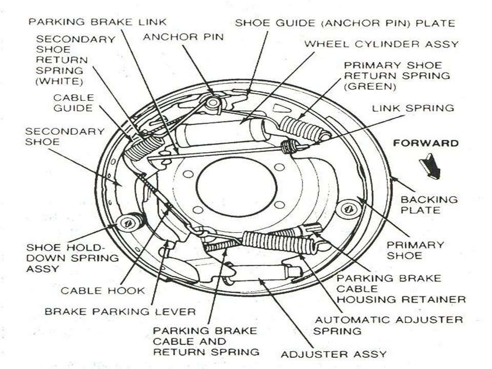
Introduction to Drum Brakes Basic operation Brake pedal pressure generated in master cylinder increases pressure in wheel cylinders Pressure builds up, wheel cylinders force brake shoes outward, to make contact with brake drums

39
Servo action Motion of drum pulls primary shoe away from anchor pin and forces it against adjuster Adjuster passes this force along to bottom of secondary shoe Motion of rotating drum jams secondary shoe against anchor pin Primary shoe “serves” secondary shoe Increases stopping power

40
leading/trailing type Both shoes operate from a dual wheel cylinder (most common) Front shoe is leading shoe Rear shoe is trailing shoe Each shoe has its own anchor pin Normally located at bottom of anchor plate Adjuster mechanism located between shoes
 Front shoe is leading shoe Rear shoe is trailing shoe Each shoe has its own anchor pin Normally located at bottom of anchor plate Adjuster mechanism located between shoes")
41
leading/trailing Brake application causes leading (front) shoe to contact drum Shoe is held by anchor pin at bottom Causes self-energization of leading (front) shoe Wheel cylinder action causes trailing (rear) shoe to contact drum
 shoe to contact drum Shoe is held by anchor pin at bottom Causes self-energization of leading (front) shoe Wheel cylinder action causes trailing (rear) shoe to contact drum")
42
There is no self-energization of rear trailing shoe except in reverse Leading shoe normally wears out faster than trailing shoe

43
Braking ratio When brakes apply vehicle dips forward putting greater stopping requirement on front wheels and less on rear Wider shoes and an increased cylinder bore in front results in 60% front braking and 40% rear braking RWD (Rear Wheel Drive) Front wheel drive (transaxle) will have a greater ratio (85% front - 15% rear or 80% front - 20% rear) to prevent rear wheel lockup
 Front wheel drive (transaxle) will have a greater ratio (85% front - 15% rear or 80% front - 20% rear) to prevent rear wheel lockup")
44
Backing Plates Round, stamped steel disc rigidly mounted to front spindles and both ends of rear axle housing Serves as mounting for wheel cylinders, brake shoes and hold down hardware Needs light coat of high-temp grease where shoes make contact

45
Brake Linings Consists of two brake shoes that have friction material fastened to shoes by means of rivets or a process called “bonding’ Shoes are constructed to be rigid

46
Brake Lining Linings are made from either organic, semi-metallic or ceramic designed to withstand high friction and high temperature

47
WARNING: Asbestos is a known carcinogen and when dealing with brake dust, approved safety methods MUST be followed!

48
Brake Drum Brake drum secured between hub and wheel Usually center section is constructed of stamped steel and outer rim of cast iron

49
Drum helps to dissipate more heat than any other part of system Must be strong enough to withstand hardest braking while at high temperatures Gives heat conductive rubbing surface and surface must not damage lining Drum inspection Check for cracks, scoring, heat checking and hard spots

50
Brake Drum Measured with drum micrometer before turning See OEM specifications for maximum oversize limit

51
Self-Adjusting Brakes Adjustment systems are of three general types Cable Link Lever

52
Emergency or Parking Brakes Mechanically held brakes, in addition to the service (hydraulic) brake system. Used only when the vehicle is stopped (unless the service brakes fail completely)
.")
53
Emergency or Parking Brakes Prevent vehicle movement when parked If service brakes fail cable operated parking brakes could be used but stopping distance drastically increases

54
Emergency or Parking Brakes Parking brakes can be easily integrated into drum brake Pedal or hand lever Cables Linkage to actuate shoes

55
Emergency or Parking Brakes Disc brake parking brakes are one of two kinds Screw or ball and ramp type integrated into disc brake caliper Small drum brake using drum cast into rotor Uses backing plate, shoes, cables and pedal or hand lever Requires specialty tool to retract piston properly

56
Advantages of Disc Brakes Resistance to heat fade Resistance to water fade

57
Advantages of Disc Brakes Straight line stops Because of clamping action, disc brakes are less likely to pull However, wheel bearing torque is critical must be to OEM specifications and same on both sides

58
Disc Brake Components Rotor assembly Flat circular steel disc secured to wheel hub May be solid or can be vented with cooling passages through it May be directional May be composite type

59
Disc Brake Components Caliper assembly Three general types - fixed caliper, sliding caliper and floating caliper Transmits hydraulic force to brake pad to squeeze them against rotor like a C-clamp

60
Disc Brake Components Brake pads Friction material such as that used on brake shoes Self adjusting

61
Fixed Caliper Has pistons on both sides of disc Some fixed caliper disc brakes have two pistons one on each side Others have four pistons two on each side

62
Fixed Caliper Caliper is rigidly attached to stationary vehicle part (anchor) Contains hydraulic passages to piston and means of bleeding system
 Contains hydraulic passages to piston and means of bleeding system")
63
Floating Caliper Caliper may have one or two pistons on one side Calipers “float” or move sideways when hydraulic pressure is applied Inner pad contacts rotor first Increased resistance causes caliper to slide sideways until outer pad contacts rotor

64
Pressure is then applied equally to both pads squeezing rotor in between

65
Sliding Caliper Sliding caliper has an anchor plate that allows caliper to slide Most are one-piece calipers with one hydraulic cylinder and one piston If used on trucks or motor homes caliper will have two or four piston designs Similar to a floating caliper in operation Basic difference is the way caliper is attached to anchor plate

66
Inner brake pad is attached to anchor plate but is free to slide Outer brake pad is attached to caliper As hydraulic pressure moves piston inner pad slides in anchor and contacts rotor Resistance causes caliper to slide causing outer pad to contact rotor Additional movement squeezes pads more tightly on rotor

67
Pads are self-adjusting There are no return springs so pads stay near rotor when released Pad Inspection and Replacement

68
Proper work habits and safe procedures will keep the technician healthy and return the disc brake system to efficient and long lasting function

69
It is best to work on one wheel at a time to prevent “popping” pistons in other caliper Keep grease, oil and brake fluid off rotor, pads, plates and outside of caliper

70
NOTE: Vehicles with ABS recommend opening the bleeder screw and pinching the flex brake hose to prevent contamination backing up into the solenoids and valves of the ABS unit

71
A proper evaluation of a disc brake equipped vehicle involves inspection and evaluation of the various wear points. A technician can then estimate the repair costs for the customer and determine the causes of failure.

72
Service Tips during Rotor Checks Parallelism Disc facing of side of disc must be parallel to each other Maximum allowable thickness variation usually about 0.0005” (0.013mm) Variations in thickness of rotor causes excessive pedal travel, pedal pulse or noise
 Variations in thickness of rotor causes excessive pedal travel, pedal pulse or noise")
73
Service Tips during Rotor Checks Rotor thickness Vehicles built since 1971 usually have specification for minimum allowable disc thickness cast or stamped into disc This measurement is minimum thickness to which disc can be refinished Most manufacturers specify a minimum and discard dimension Minimum thickness is a machining limit allowing for additional wear in service Always check for correct specifications for vehicle being serviced

74
Inspect pads for wear Check for pad thickness according to OEM specifications Some have wear indicators which will be exposed when wear limit is reached “Squealer” indicators are metal strips attached to pad Some use sensors that trigger a dash warning light Pad Inspection & Replacement

75
Check for pad taper Pads should be replaced if taper across entire face of pad is more than allowed Check pads for contamination Replace if necessary Check pads for freedom of movement Some pads are crimped to caliper Pad Inspection & Replacement

76
NOTE: After the installation of the pads and before the car is driven, insure that the pads are pushed against the rotor by the piston. Also re-service the master cylinder if necessary.

77
Install new pads, reinstall clips, pins, anti- rattle springs Install calipers (if removed) Lubricate slide areas with high temperature grease Pump brake several times before attempting to drive vehicle - brakes may not work at all until this is done!!! Pad Inspection & Replacement

Similar presentations