Download presentation
Presentation is loading. Please wait.

1
Clutch Fundamentals Chapter 69

2
Objectives Describe the basic clutch parts
Explain the operation of the clutch Compare differences in clutch design Describe the different methods of releasing the clutch

3
Introduction Clutch Found on vehicles with manually shifted transmissions Disengages engine from transmission Releases engine from transmission during gear shifts Driver controls clutch application from inside the vehicle with a clutch pedal Engine does not make sufficient torque at lower rpm to be able to move the car Clutch must gradually couple rear wheels to engine

4
Clutch Parts and Operation
Flywheel Pressure plate Friction disc Release mechanism Clutch disc pushed against flywheel with enough force Disc will rotate with flywheel

6
Clutch Disc Characteristics
Clutch hub: inner part of disc and has splines Torsional dampers: absorb shock Clutch disc has facings made of friction material Contain molded or woven asbestos Facings riveted to both sides of cushion plate Cushion plate is riveted to disc plate Clutch is engaged: air is trapped in grooves Clutch is released: trapped air pushes disc away from pressure plate and flywheel

7
Pressure Plate Pressure plate is cast iron plate
Part of cover assembly Cover assembly is bolted to the flywheel Clutch disc is wedged between pressure plate and flywheel Space between pressure plate and flywheel is less than thickness of clutch disc Engine and transmission are physically connected when clutch pedal released

8
Types of Clutch Covers Clutch covers types Coil spring Diaphragm
Other designs are less common

9
Coil Spring Clutch Pressure plate springs are preloaded when clutch cover assembled at factory Springs are compressed further when cover assembly is bolted to flywheel Clutch is engaged: pressure plate exerts pounds force on the disc Disc worn out: ten percent more torque carrying capacity left in the clutch than engine can deliver

10
Release Levers Attached to cover assembly at pivot points
Pushing clutch pedal moves pivot lever Pulls pressure plate away from flywheel Advantages of coil springs More coil springs can be installed Centrifugal force applies clutch more tightly Disadvantages of coil springs More pedal pressure required Clutch applied less heavily as disc wears Must be precisely balanced after assembly

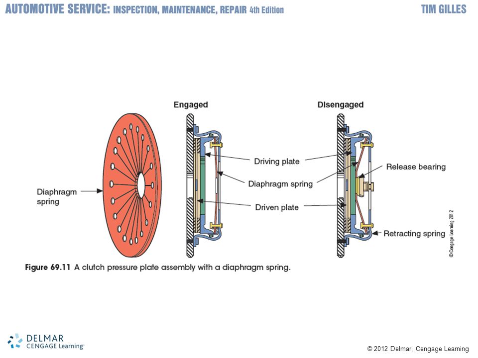
11
Diaphragm Clutch Diaphragm spring replaces release levers and coil springs Diaphragm pivots off pivot rings when clutch pedal is depressed Advantages Requires less effort and takes up less space Spring pressure becomes greater as disc wears Well balanced Dual mass flywheel: reduces noise and vibration Allows smoother gear shifting

13
Pilot Bearing or Bushing
Engine side of transmission input shaft Supported by sealed pilot bearing or sintered bronze bushing Some FWD transaxles do not use pilot bearing

14
Release Bearing Allows pressure plate release mechanism to operate as crankshaft rotates Slides on the front transmission bearing retainer Lubricated and sealed at the factory Self-centering release bearings Used on FWD cars Do not use pilot bearing in the crankshaft Specially designed release bearings Found on vehicles that have pressure plates that pull to release

15
Clutch Fork Release bearing hub has provision to attach it to the clutch fork Clutch fork fits between release bearing and clutch cable or linkage Has pivot shaft, pivot ball, or raised area in the bell housing off which it pivots

17
Clutch Release Methods
Clutch pedal operates clutch fork using: Linkage Cable Hydraulic cylinders Clutch start switch Included on the clutch pedal Prevents engine from starting unless the clutch pedal is depressed

18
Clutch Cable Some cars use a cable to operate the clutch
Adjustment remains the same as the engine moves Develop friction and wear with repeated use Linkage can push on clutch arm Cable can only pull on it Pivot point of fork Must be on the outside of input shaft Away from cable end

20
Hydraulic Clutch Operation
Characteristics Hydraulic clutches are found on many manual transmission–equipped vehicles Master cylinder input piston: connected to clutch pedal Output piston: located in reaction or actuator cylinder (i.e., slave cylinder) Difference between clutch master cylinder and brake cylinder Clutch master cylinder does not have a fill port or residual check valve
 Difference between clutch master cylinder and brake cylinder. Clutch master cylinder does not have a fill port or residual check valve.")
21
Clutch Free Travel Free travel
Usually adjusted to about one inch at pedal Newer vehicles have self-adjusting clutches Maintain contact between release levers and release bearing Standard release bearings Don’t remain in constant contact with clutch cover Some vehicles have self-adjusting cables Spring-loaded sector gear pinned to pedal arm Clutch released: pawl lifted and raised

24
Dual Clutch Transmissions
Being used by several manufacturers Two clutches connect to two separate geartrains within one transmission housing

Similar presentations