Download presentation
Presentation is loading. Please wait.

1
Futera III Wiring Diagram Presentation 42-0403-G

2
Digital Text Display Tekmar Control RM7895C Honeywell Connection Terminal Strip Control Cabinet

3
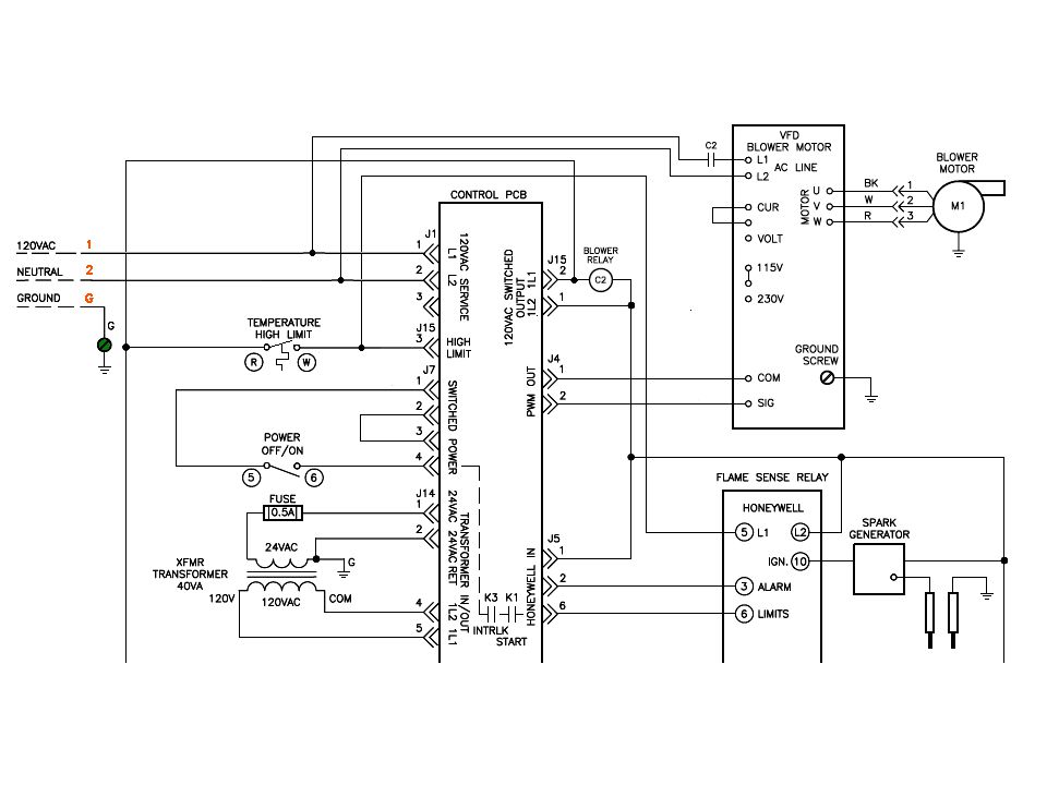
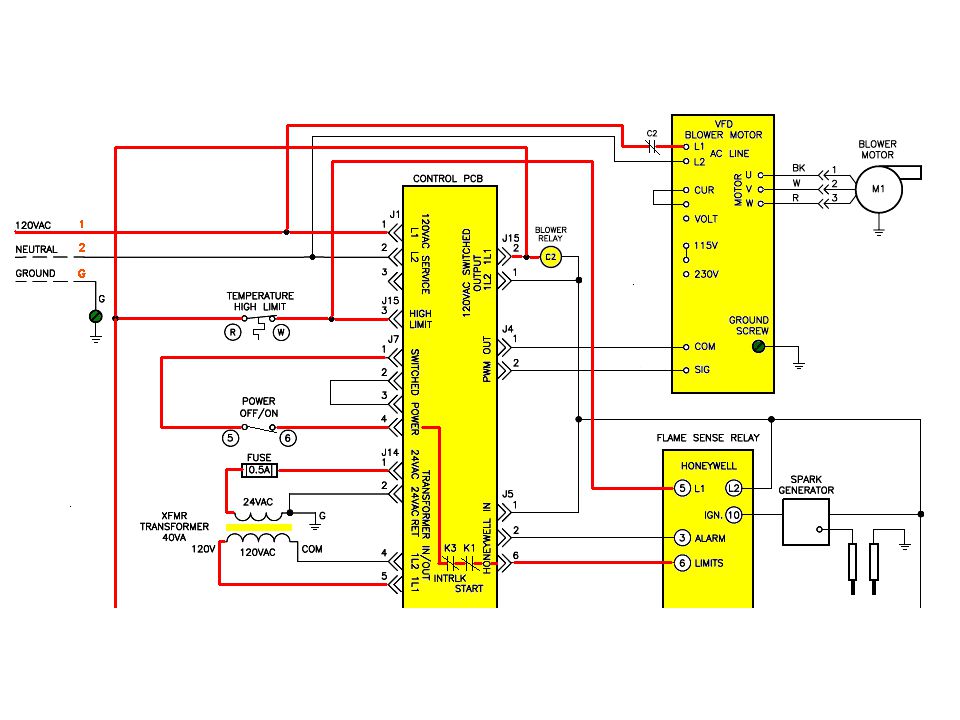
Main Control Board Frequency Drive Power Supply

4
120 VAC Supply

5
Main BoardFlame Safeguard Light Display Tekmar

6
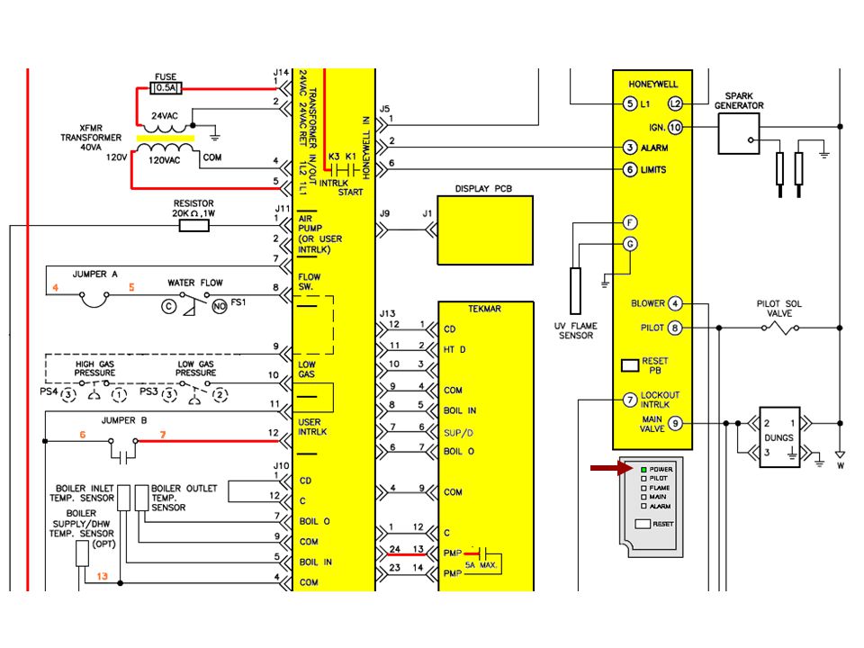
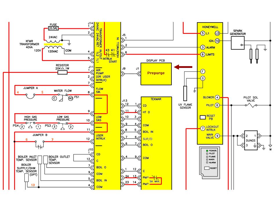
LWCO Interlock

7
Boiler Enable

8
Flame Safeguard Main Board Tekmar

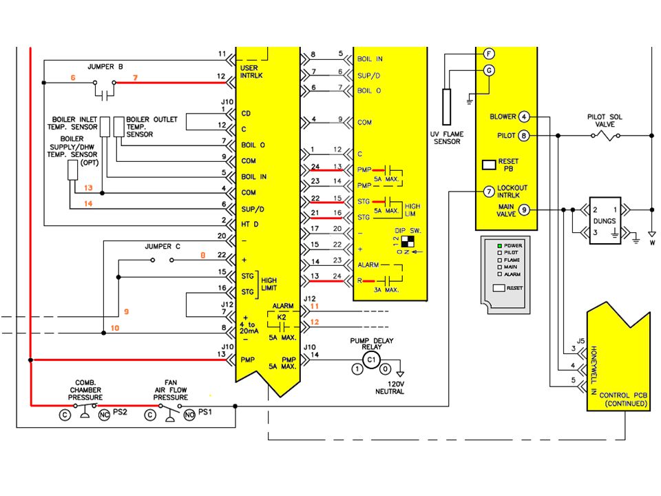
9
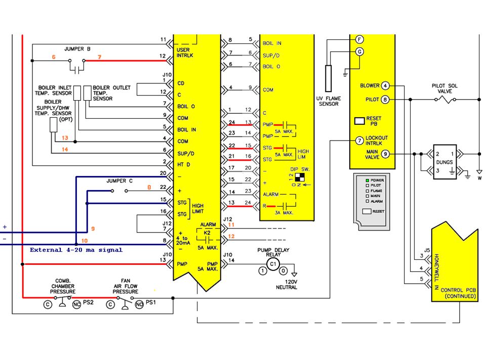
4-20mA Modulation Signal (Mode 4)
")
10
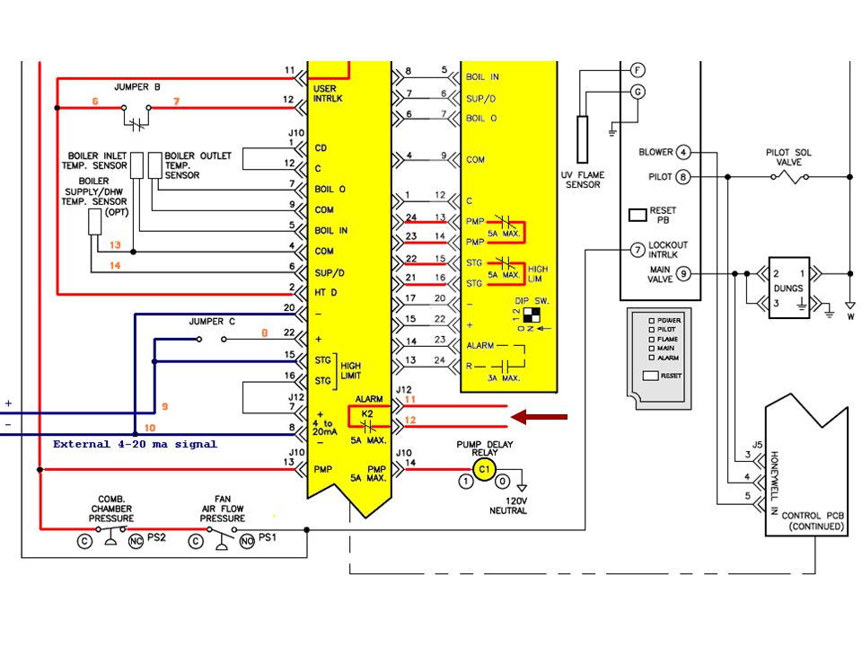
Boiler Alarm Contacts

11
Supply/DHW Temp. Sensor (Mode 2 and 3)
")
12
Pump Connections

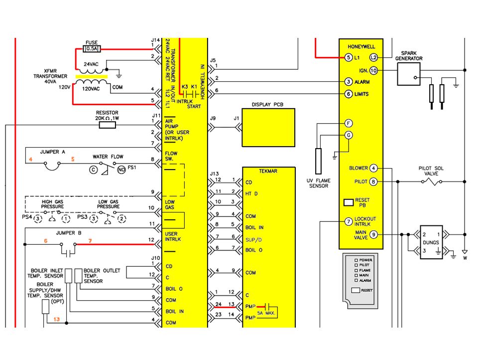
14
Power Supply

15
Power Switch On

17
C2 Contact Closes

19
Hi-Limit OK

25
External 4-20 ma signal

29
Call For Heat

30
Heat Demand To Tekmar

33
Pump/STG Contacts Close

34
Pump Energizes

37
Switch Reset

40
Flow OK

42
Interlock Circuit Made

43
Limit String To Flame Safeguard

49
Air Flow Switch Makes

50
Lockout Interlock Satisfied

51
10 Second

52
10 Sec. Pilot Trial For Ignition

53
Pilot Failed To Light

61
10 Sec. Pilot Trial For Ignition

62
Flame Sensed

63
10 Sec. Main Gas Trial For Ignition

65
Boiler Inlet-Outlet Sensors

66
Supply/DHW Sensor Modes 2 & 3

68
Hi-Limit Trips

71
THANK YOU! We look forward to working closely with all of you in the near future:

Similar presentations


/40GXC(Q) Service Training Sizes 18 and 24K.>")


>")


 Training Module>")
