Download presentation
Presentation is loading. Please wait.

1
“CONTROL SYSTEM” CONTROL MOVEMENT OF TRAIN AND SIGNALLING

2
INTRODUCTION Basic objective of signalling is to control the movement of train A view to ensure safety by preventing accidents To achieve the goal three aspects is important Safety Speed Traffic density

3
INDIAN RAILWAY NETWORK
Despite the phenomenal increase in traffic, the number of train accidents has come down from 464 in to 234 in In , there were195 accidents, the lowest since 1960's. Indian railways, the largest rail network in Asia and the world's second largest under one management, are also credited with having a multi gauge and multi traction system.

4
INDIAN RAIL NETWORK The railways have 7566 locomotives, 37,840 coaching vehicles, 222,147 freight wagons, 6853 stations, 300 yards, 2300 goodsheds, 700 repair shops, 1.54 million workforces. Indian Railways runs around 11,000 trains everyday, of which 7,000 are passenger trains.

5
Various control system that governs the movement of train
“One engine system only” system “following train” or “time interval system” “pilot guard” system “ train staff and ticket” system “absolute block” or “space interval” system “automatic block” system also called automatic signalling” “Centralized traffic control” system {C T C} “automatic train control” system {A T C} “cab signalling and continuous automatic train control with automatic train protection anti collision system

6
ONE ENGINE ONLY SYSTEM When railways first started, company probably possessed only one engine and few carriages. Only one train is therefore allowed to run at any any time, and question of any collision do not arise. Unless the engine has returned no other engine can be sent on line. This system is suitable for small section

7
FOLLOWING TRAIN OR TRAIN INTERVAL SYSTEM
In this method, a fixed interval of time is maintained between departure of consecutive train. This fixed time is calculate on basis of sufficient distance that is need to be kept between the train. This method is still used in case of emergencies such as failure of block telegraph, telephone and method is also used on short double line branches

8
PILOT GUARD SYSTEM When on single lane the system of communication between two office does not exist , pilot guard system Of working is used . Under these system one person known as “pilot guard” accompanies the train (or he may also give written authority to proceed into the section) to the station ahead and returns after adequate interval (15 minutes) to the same station with another train. Thus the pilot guard system of both one engine only and following train system in its working
 to the station ahead and returns after adequate interval (15 minutes) to the same station with another train. Thus the pilot guard system of both one engine only and following train system in its working.")
9
This system under specific occasion such as
A failure of block-telegraph or telephone system in case of single line . In double line, when one line is out of order and other line is to be up and down trains

10
TRAIN STAFF AND TICKET SYSTEM
It is similar to pilot guard system in which there is only one and only one authority for permitting train to enter the section, the train staff. In thus case the train staff or ticket issued by the station master where the train staff is positioned at that time, take the place of pilot guard on his ticket as the authority for taking the train into the section. Train can follow one another at fixed intervals from the station where train staff is situated

11
ABSOLUTE BLOCK OR SPACE INTERVAL SYSTEM
This system is most extensively used in INDIAN RAILWAYS, about 90% of train are controlled by this system. In this system entire track is divided into section called “blocks section”, separated by block station, each station provided with block instrument. These instrument are used to show whether the section ahead is clear or reserved from train. These block are linked both by telegraphically for operation of block instrument and telephonically for verbal exchange of information. Block station is under charge of a station master.

12
ESSENTIALS OF ABSOLUTE BLOCK SYSTEM
No train should leave the station , unless permission to do so has been received from block station in advance. No train should be given permission to approach a block station In case of double line, when the line on which train being run is clear upto an adequate distance beyond the first stop signal at station at which permission is being given. In case of single lane, when line is free of train and is clear upto adequate distance beyond the first stop signal and is free from train running in opposite direction or will be free of trains after the complete arrival of train going towards the station to which the permission is being given . These are essentials for reception of trains.

13
When two train are on same track and running in same direction, the permission to approach for the second train should not be given unless The first train has arrived at proper position within the home. All the signals behind the first train have been put back to “on” position. The line is clear up to first stop signal of the station but also for an adequate distance beyond it. All the switches or points have been set, facing points locked and trailing points bolted for the second train.

14
BLOCK INSTRUMENT FOR DOUBLE LINE

15
Block Instruments: Instruments to signal for each line are provided at signalboxes where Double Line Block system is in operation. The instruments consist of: Two dials A plunger A black button A switch handle A bell The left hand dial has a red needle referring to trains approaching the signalbox. The right hand dial has a black needle referring to trains departing the signalbox. The needles have two positions: "Cleared" means train cleared and "On Line" means train on line. The plunger is used for giving the code signals on the bell. The bell at the signalbox at the other end of the section will sound once each time the plunger is depressed. The black button controls the black indicating needle and is pressed in order to place the indicator to the "Train on Line" position or restore it to the normal position. The switch handle has two positions "On" and "Off" corresponding to the two positions of the indicating needles "Cleared" and "Train on Line". The normal position of the switch handle is 'Off' and must be placed to the 'On' position before acknowledging the 'Is Line Clear?' or 'Section Clear but Station or Junction Block' bell signals. The switch handle must remain in the 'On' position until necessary to be placed in the 'Off' position. It must be placed in the 'Off' position prior to giving the 'Train Arrival' signal or acknowledging the 'Cancelling' signal.

16
Different sets of token are used for different block section
In case of double lane, each of the block instruments is provided with two dials one for dispatch and other and other for receiving the train. One dial for each track so incase of double lane track, one train on each track can remain in a block at a time. For a single lane track, one train can remain in track. In single-track, a token is taken out by the station master given to the train guard to indicate block section is clear. In double line track, indication of track being clear or engaged is given by simply turning the key knob which deflects the needle on the dial accordingly.

17
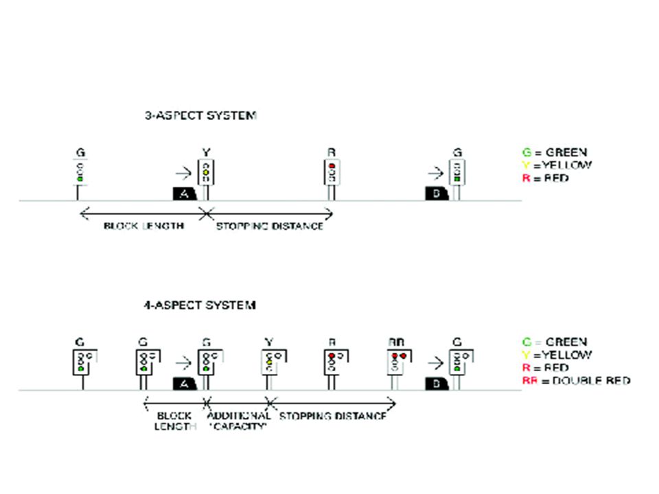
AUTOMATIC BLOCK SYSTEM (OR AUTO SIGNALLING)
This system is improved version of absolute block system and avoids the possibility of accidents due negligence on part of human beings. In this particular system the signals are actuated by the trains themselves and therefore, the trains can follow each other between two stations. The section between two station is divided into number of blocks (one block 5 to 7 Km length. An electric currents is conveyed through electric currents curcuited tracks. When a train enters a particular block, the electric current put the signal in danger position ( red light ), for the particular block until the train has gone nearly two block away.
, for the particular block until the train has gone nearly two block away.")
19
ADVANTAGES OF AUTOMATIC BLOCK SYSTEM
Human error is eliminated which leads to grater safety. reduce operation cost. Increase traffic density. No block instrument is required. Incase failure of signals due to current, the signals are made to bring to danger position.

20
Computer based Centralised Traffic Control (CTC) Train Management and Information System (TMS):
Centralization of operation of all points and signals at various station and on section of railway at one single location and concentrating the control over all points and signal indication into hands of single official. This official thus has control over traffic movement over the section

21
C T C system was introduced in U S A , and introduced in N F & N E railway in India recently.
In this system control panel is used which illuminated track diagram showing relative position of signals , points and track circuits together with their reference number. There are number of thumb switches below the illuminated track diagram for the control of points. Below the thumb switches, the signal thumb switches are mounted to operate signal in different position .

23
There are switch to determine direction of movement of train and the signal in opposing direction remain in danger position. Dispatcher makes all the arrangement for crossing, points and signals, can also be done in advance and is free to do office works. This system increase the track capacity, and is also capable of detecting defects of track. Train can run at maximum speeds as the driver has not to give any signals because driver is warned by means of whistle or red-light in his cabin if approaching to stop signal , even the driver fail to obey the signal brakes will be automatically applied.

24
Computer based Centralised Traffic Control (CTC) and Train Management and Information System (TMS):
The work on Ghaziabad-Kanpur section with CTC/TMS will be completed by 2009 under the German Bank funded project. This system provides efficient rail services, giving the commuters accurate information on real time basis about the status of train services. All train movements are displayed on a video projection screen in control room. TMS on Mumbai Suburban section of Western Railway has been commissioned. The work of TMS on Central Railway is likely to be completed by 2009.

25
Automatic Train Protection and Warning System
Automatic Train Protection and Warning System is an aid, which provides audiovisual warning to the driver and prevents him from passing signals at danger. Presently, an AWS is working on Mumbai suburban area of Western and Central Railways. AWS on 128 kms stretc . Railways have taken the initiative for provision of Train Protection and Warning System TPWS for providing an aid to driver to prevent cases of ‘Signal Passing at Danger’ (SPAD) as a safety measure. TPWS is being provided over 250 Route Kilometres on important sections of Northern Railway, North Central Railway and work on Southern Railway is in progress.
 as a safety measure. TPWS is being provided over 250 Route Kilometres on important sections of Northern Railway, North Central Railway and work on Southern Railway is in progress.")
27
ATP signalling codes contained in the track circuits are transmitted to the train. They are detected by pick-up antennae (usually two) mounted on the leading end of the train under the driving cab. This data is passed to an on-board decoding and safety processor. The permitted speed is checked against the actual speed and, if the permitted speed is exceeded, a brake application is initiated. In the more modern systems, distance-to-go data will be transmitted to the train as well. The data is also sent to a display in the cab which allows the driver of a manually driven train to respond and drive the train within the permitted speed range. At the trackside, the signal aspects of the sections ahead are monitored and passed to the code generator for each block. The code generator sends the appropriate codes to the track circuit. The code is detected by the antennae on the train and passed to the on-board computer. As we have seen, the computer will check the actual speed of the train with the speed required by the code and will cause a brake application if the train speed is too high.

29
DELHI METRO RAIL The underground sections have
Centralized Automatic Train Control (CATC) comprising Automatic Train Operation(ATO) Automatic Train Protection (ATP) Automatic Train Signalling (ATS)
 comprising Automatic Train Operation(ATO) Automatic Train Protection (ATP) Automatic Train Signalling (ATS)")
30
ANTI COLLISION DEVICE Anti Collision Device: An Anti Collision Device (ACD) also called “Rakshakavach” has been developed by Konkan Railway Corporation with their technical partnertem kernex microsystem to prevent Collisions at high speed, which might be caused due to mistakes committed by human agency at time of failure of Signalling and Interlocking Systems.

31
A C D ACDs have knowledge embedded intelligence. They take inputs from GPS satellite system for position updates and network among themselves for exchanging information using their data radio modems to take decisions for timely auto-application of brakes to prevent dangerous ‘collisions’, ACDs fitted (both in Locomotive and Guard’s Van of a train) act as a watchdog in the dark as they constantly remain in lookout for other train bound ACDs, within the braking distance required for their relative speeds
 act as a watchdog in the dark as they constantly remain in lookout for other train bound ACDs, within the braking distance required for their relative speeds.")
32
They communicate through their radios and identify each other
They communicate through their radios and identify each other. If they happen to find themselves on the same track and coming closer to each other, they automatically restrain and stop each other, thereby preventing dangerous head-on and rear-end collisions. Loco ACD of a train also applies brakes to reduce the train speed either to 15 km/h if on approach it receives a message from other train bound ACD that has stopped in a block section on adjacent track (and driver of that train has yet not communicated that things are ‘Normal’) or to bring the train to a stop if train bound ACDs of other train are radiating ‘train parted’ message thereby preventing dangerous side collision that may occur due to infringement of adjacent track by a stopped or a ‘parted’ train, respectively.
 or to bring the train to a stop if train bound ACDs of other train are radiating ‘train parted’ message thereby preventing dangerous side collision that may occur due to infringement of adjacent track by a stopped or a ‘parted’ train, respectively.")
33
Mr B Rajaram

34
A C D at Level crossings Loco ACD on receipt of ‘Gate Open’ input from Gate ACD (provided at non-interlocked level crossing), applies brake to regulate its train speed. Gate ACDs fitted at manned and un-manned level crossings also give audio-visual ‘Train Approach’ warning to road users if an Loco ACD also gives ‘Station Approach’ alert to the driver and regulates its train speed when it receives information from Station ACD to this effect, namely, either main-line is occupied by a train OR a load stabled on it and not fitted with ACD OR if route for train reception is not set for main line ACD fitted train approaches them
, applies brake to regulate its train speed. Gate ACDs fitted at manned and un-manned level crossings also give audio-visual ‘Train Approach’ warning to road users if an Loco ACD also gives ‘Station Approach’ alert to the driver and regulates its train speed when it receives information from Station ACD to this effect, namely, either main-line is occupied by a train OR a load stabled on it and not fitted with ACD OR if route for train reception is not set for main line ACD fitted train approaches them.")
35
ACD Project commissioned in Indian Railway (Work sanctioned for another 3500RKm)
Route Kms = 1760, Stations = 202 1 Fixed ACDs – Station ACD, Level Crossing ACD, ACD Repeater, Locoshed ACD etc. 578 2 Mobile ACDs - Loco ACD Guard ACD (Passenger) Guard ACD (Freight) 567 82 133 Total 1360
 Guard ACD (Freight) Total")
36
Working of “on-board” System
GPS Satellites Location Speed Course of Travel Time UHF Data Radio Modem Gate UNIT GPS Receiver Inter-ACD Radio Communication Loco Working of “on-board” System Receive inputs from satellites, communicate with Gate Unit using radio modems & use intelligence to act – To prevent ‘dangerous’ Collisions

37
Unit for Locomotive ( L 435 x W 203 x H 342 mm )
")
38
Location Box for Gate Unit

39
Driver Console ( L215 x W80 x H125)
DRIVER'S CONSOLE L 1 9 : 2 6 SOS ACD-OK ACD-M KONKAN RAILWAY CORPORATION LTD.

40
Scenario - Gate Approach
S T G A T E A P P R O A C H 1 9 : 2 6 Train approaches the Gate ST 346 At approximately 2000m from the Gate ‘Gate Approach’ message and audio buzzer appears for 10 seconds

41
Scenario – Gate OPEN S T G A T E O P E N 1 9 : 2 6 Level Crossing Gate ST 346 is detected to be OPEN – Audio Visual Indication is automatically activated to draw the attention of the Driver and brakes are applied to reduce the speed to 15 Km/h.

42
FUTURE OF “A C D” IN INDIA
Pilot project of "Provision of ACD Network" has been successfully commissioned recently on the Northeast Frontier Railway (of Indian Railways), covering 1736 Route km (of its Broad Gauge route). Final commissioning trials of ACD network installed on 760 km of Konkan Railway route is presently underway. Anti Collision Device (ACD), which is an on-board train protection device and also the first ever device in the world indigenously developed by Konkan Railway with their Techical Partner Kernex Microsystems (I) Ltd, will be in place by 2013 on the entire Indian Railway network so as to reduce chances of Train collisions
, covering 1736 Route km (of its Broad Gauge route). Final commissioning trials of ACD network installed on 760 km of Konkan Railway route is presently underway. Anti Collision Device (ACD), which is an on-board train protection device and also the first ever device in the world indigenously developed by Konkan Railway with their Techical Partner Kernex Microsystems (I) Ltd, will be in place by 2013 on the entire Indian Railway network so as to reduce chances of Train collisions.")
Similar presentations


 Network (Raksha Kavach TM ) … A Train Collision Prevention System (TCPS) Ajaykumar A. Bhatt, IRSSE Chief Signal & Telecommunication.>")

 Transit ITS CEE582.>")