Download presentation
Presentation is loading. Please wait.

1
The Design: Totally bolted, electrically isolated 6 top and 6 bottom inboard flange holes, with tapped holes in one flange and a thru holes in mating flange “Reasonably” tight fitting bushings Nut options: Superbolt, Hex, Hydraulic Nut w/ lock nut C – C Interface

2
Design Issues: Physical ACCESS - Initial installation of bolting hardware - Re-Torquing of nuts (for all flange interfaces) Choice of ACCESS location - Top and bottom, inboard, between TF coils - Top and bottom, outboard, at “B” coil - Top and bottom, outboard, thru back of “C” coil Risks associated with ACCESS location Measuring and installing bushings C – C Interface
 Choice of ACCESS location - Top and bottom, inboard, between TF coils - Top and bottom, outboard, at B coil - Top and bottom, outboard, thru back of C coil Risks associated with ACCESS location Measuring and installing bushings C – C Interface")
3
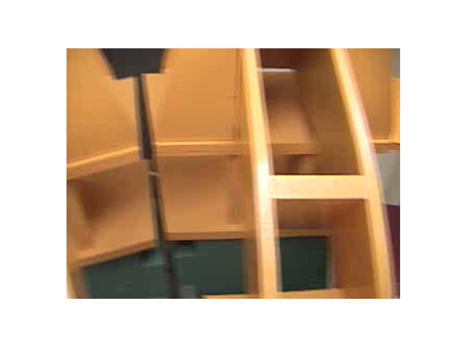
Field Period In-board Flanges Mockup (Including C - C) C - Coil (Green) B - Coil (Red) A - Coil (Blue) C–C Joint A–A Joint
 C - Coil (Green) B - Coil (Red) A - Coil (Blue) C–C Joint A–A Joint")
4
Checking access for welding Modular Coils Flanges Assembly Mockup C-C A-A

7
Top and bottom, inboard between TF coils: C – C Interface

9
Top and bottom, inboard between TF coils: C – C Interface Visually clear line of sight, directly above and between TF openings on either side Easiest access and most comfortable working position Lowest risk of a worker damaging any external tubing, headers, electrical hardware, etc… Longest distance to reach the bottom-most nut Access opening is more restricted

10
Top and bottom, outboard at “B” coil: C – C Interface

12
Top and bottom, outboard thru back of “B” coil: C – C Interface Most direct access to nuts Shortest distance to reach the bottom-most nut (19”), good possibility of a worker (small in stature, with long arms) being able to use a hands-on approach when installing bolt kit High risk of a worker damaging some of the external tubing, headers, electrical hardware, etc… by having to climb around the shell and lay horizontally and try to wedge down into the opening Does not allow a direct line of sight for worker, video camera / light system will be needed
, good possibility of a worker (small in stature, with long arms) being able to use a hands-on approach when installing bolt kit High risk of a worker damaging some of the external tubing, headers, electrical hardware, etc… by having to climb around the shell and lay horizontally and try to wedge down into the opening Does not allow a direct line of sight for worker, video camera / light system will be needed")
13
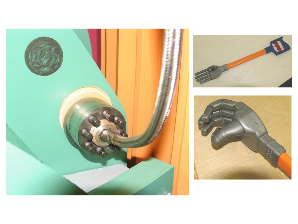
Measuring, fabricating, installing bushings: C – C Interface A video system (flexible cable) with lighting will be needed to read the bushing gage for measuring hole eccentricity An alternative is to wrap the outer gage surface with litmus or fuji paper so when the gage rotates and stops, a line marks where it touches the hole inner diameter The finished bushing: - Slides down the strain gage sheathing onto stud - Is oriented accurately to the hole - Slightly inserted into flange hole - Bearing washer, hex nut slides down cable - Nut is tightened to press the bushing into hole Bushing installation nut is removed, permanent nut is re-installed with complete washer set
 with lighting will be needed to read the bushing gage for measuring hole eccentricity An alternative is to wrap the outer gage surface with litmus or fuji paper so when the gage rotates and stops, a line marks where it touches the hole inner diameter The finished bushing: - Slides down the strain gage sheathing onto stud - Is oriented accurately to the hole - Slightly inserted into flange hole - Bearing washer, hex nut slides down cable - Nut is tightened to press the bushing into hole Bushing installation nut is removed, permanent nut is re-installed with complete washer set")
14
Proposed R&D: C – C Interface Feasibility study will be to measure and install a bushing in an enclosed “box” using manipulator, video camera mounted in side and light inside. - Determine most accurate method of measuring bushings - Determine how to orient / register bushing with hole - Determine if bushing can be “seated” using a nut Design and development stage will involve: - Manipulator fabrication or modifications - designing controls for moving, rotating, etc… video system Field testing ideally involves using a C-C assembly in a vertical position with a B coil to see if there are any surprises due to mistakes in the coil castings - and also using the “actual”, out-of-round flange holes Prove feasibility of making and installing a bushing Prove feasibility of making and installing a bushing 1 Month 2 Months Design, develop, and acquire necessary tools and hardware – identify and acquire necessary video / lighting components Design, develop, and acquire necessary tools and hardware – identify and acquire necessary video / lighting components Field test tooling, video equip to make and install bushings Field test tooling, video equip to make and install bushings 1 Month Manpower – PJ (.5), Gary (.25-.5), Joe (.25), Jim (.25), Bob (.25) = 1.5 – 1.75 for 4 months
, Gary (.25-.5), Joe (.25), Jim (.25), Bob (.25) = 1.5 – 1.75 for 4 months.")
15
Conclusions: C – C Interface Based on the design of 6 top and 6 bottom holes, 4 of the 6 holes appear to be accessible for making tight fitting bushings and bolting the joint with a reasonable effort. 2 of the 6 holes will require a difficult and time consuming effort to accomplish the bolted design. R&D tasks have been identified and planned to insure the success of the bolted design. Bottom Line: It is feasible to make the bolted C-C joint

Similar presentations