Download presentation
Presentation is loading. Please wait.

1
Electrical subsystem Manual vs Automation

2
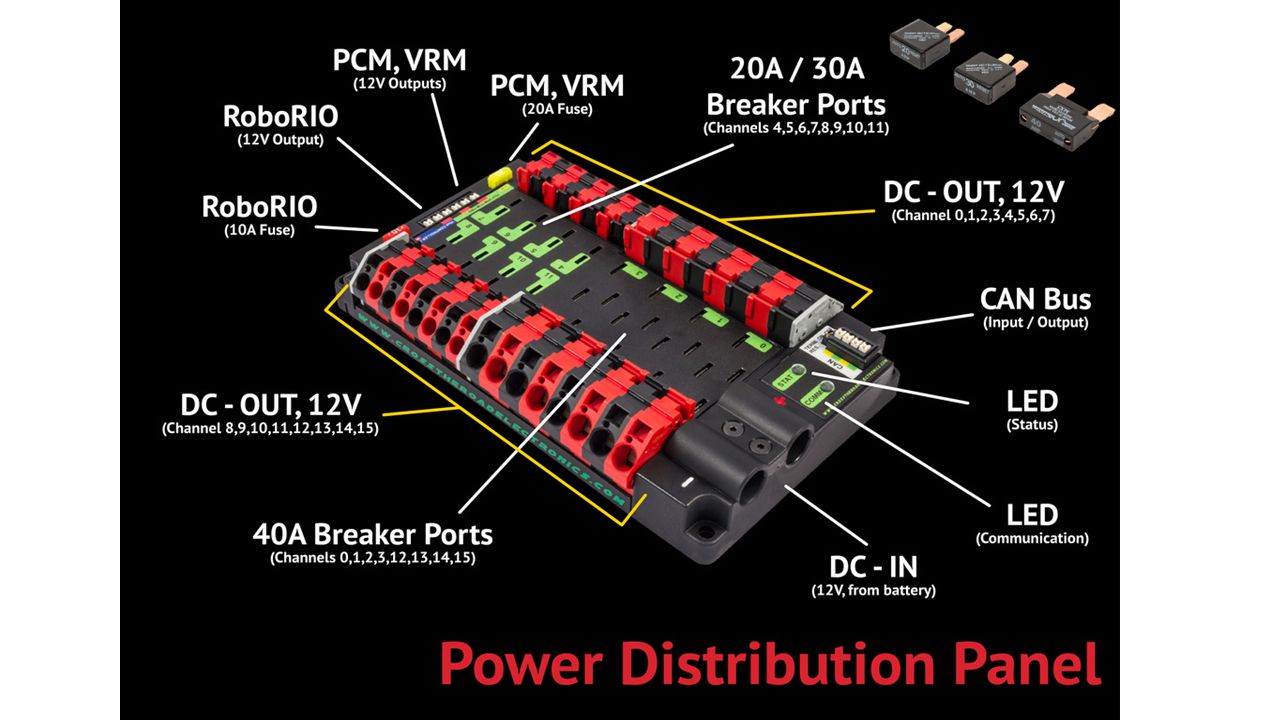
Power Distribution Diagram
Make motor in the corner smaller to resemble scaling Make CPU darker Put red/black lines closer together Put currents for the branches – CPU = 20 A, Spike = 20 A, Speed Controller = 40 A,

3
FIRST Power Distribution Diagram

4
Battery Voltage: 12 Volts Nominal Weight: 13 Pound Chemistry: Lead-Acid (Gel) Capacity: 18 Ah Ah when rated for 1 hour Current: Nominal 150 A Power: ~1600 Watts at 150 A Can supply over 700 amperes of current when terminals are shorted. Explain battery safety Two hands because it is heavy Nylon stop nut is a tip Remove #10 screw - done Smaller than a car battery Fix spacing Remove bullet point for take precautions Change text NEED TO SAY Terminals are separate Wrench Welded together

5
Robot Power Switch Used to turn robot on and off, including emergency shut off Also a 120 amp circuit breaker Must be placed in an accessible location Not located accessibly Should be in an easy-to-access area On/Off switch Fire hazard Retitle to robot power switch 120 amp circuit breaker Control should be changed to limit Exceed 120 amps and it will break Remove bullet points when not necessary High current switch Handles high enough current Primary importance Doubles as a circuit breaker

9
Power Distribution Diagram
18AWG 100A 6AWG 40A 20A 12AWG 18AWG Make motor in the corner smaller to resemble scaling Make CPU darker Put red/black lines closer together Put currents for the branches – CPU = 20 A, Spike = 20 A, Speed Controller = 40 A,

10
American Wire Gauge Wire thicknesses are based on the AWG (American Wire Gauge) System AWG wire thicknesses are based on number of wire draws: Higher gauge = thinner wire Explain safety concerns when using smaller diameter wires

11
American Gauge System Draw Plate 1 Draw Plate 2 Undrawn Wire
oAll wire from battery to PD have min #6 AWG (4.11mm) wire <R39 & Fig.4-8> o40 amp breakers have min #12 AWG (2.052mm) wire <R44> o30 amp breakers have min #14 AWG 1.628mm) wire <R44> o20 amp breakers have min #18 AWG (1.024mm) wire <R44>
 wire <R39 & Fig.4-8> o40 amp breakers have min #12 AWG (2.052mm) wire <R44> o30 amp breakers have min #14 AWG 1.628mm) wire <R44> o20 amp breakers have min #18 AWG (1.024mm) wire <R44>")
12
RoboRIO

13
RoboRIO 2014 RoboRIO Power 6.8-16V via PDP Processor
Dual-Core ARM Cortex™-A9 at 667 MHz . Memory 256MB System. 256MB Storage. PWM 10 Ports USB 2 USB Host and

14
Problem! The roboRIO cannot directly control the motors. Solution:
Cannot provide enough power Solution: Motor Controllers Relays Electronic Speed Controllers

15
Connections Motor Motor Controller roboRIO Copper Wire

16
Spike Relays Relays close or open the circuit based on signals from the cRIO. Contains two independently controlled SPDT* relays arranged in an H-Bridge *SPDT = Single Pole Double Throw switch

17
How an H-Bridge Works ` S1+S4 FULL FORWARD S3+S2 FULL REVERSE S1+S3
BRAKE S1 S3 MOTOR S2 S4 Ground

18
Electronic Speed Controller (ESC)
Control the amount of power sent to the motors in addition to direction that motor turns. Two types of ESC’s: Talon SRX Victor SP 2004+ Victor 2009+ Jaguar

19
Comparison Talon SRX Victor SP $79.99 $59.99 Features Similar Features
CAN & PWM communication 6-28V Small & light Embedded power and output Completely Sealed 12V Nominal PWM communication 6-16V

20
Size Comparison

21
Speed Controller Communications
There are two ways to communicate with the Jaguar ESC Servo Wire Uses Pulse Width Modulation CAN-bus Uses “Message based protocol” (like Ethernet)
")
22
Difference between CAN and PWM Wiring
ESC roboRIO ESC cRIO (Daisy Chaining)
")
Similar presentations


 MVRT. Main Circuit Breaker Connected to the red wire (power) of the battery When turned off, all power is cut off and robot.>")


 40 amp Circuits (4) (6) 20/30 amp Circuits (6)>")


