Download presentation
Presentation is loading. Please wait.

1
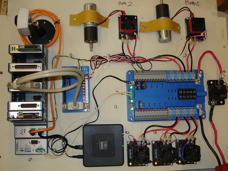
Wiring the new control system MVRT 2010 – 2011 Season

3
Basic Wiring Principles Color convention for insulation (according to rules) –Power = red, white, brown –Ground = black, brown Use right size (gauge/diameter) cables –Big wire = smaller gauge = more current Basic types –Solid – single wire –Stranded – multiple smaller wires twisted together –Jacketed – multiple insulated wires with an outer cover
 –Power = red, white, brown –Ground = black, brown Use right size (gauge/diameter) cables –Big wire = smaller gauge = more current Basic types –Solid – single wire –Stranded – multiple smaller wires twisted together –Jacketed – multiple insulated wires with an outer cover")
4
FIRST Wiring Rules

5
Robot Battery 12V Lead-Acid Battery Connects to power block and main circuit breaker Powers all functions of robot

6
Wiring diagram Battery

7
Main Circuit Breaker Turns robot on and off To turn it off press the red button on the top To turn it on close the switch Connects the battery to the power distribution board Normally use the red power cable from the battery to the breaker

8
Wiring diagram Battery Circuit breaker

9
Power Distributor Board Distributes power to all the electrical components Makes sure not too much current is drawn and everything is well connected Connects to everything that requires power

10
Wiring diagram Battery Circuit breaker Power distribution board

11
Compact RIO Controller (cRio) Brains of Robot Gets power from the power distributor board Sends power and signal to the Digital Sidecard and the Wi-Fi interface Connects via Wi-Fi to the driver station and the robot
 Brains of Robot Gets power from the power distributor board Sends power and signal to the Digital Sidecard and the Wi-Fi interface Connects via Wi-Fi to the driver station and the robot")
12
Modules and Bumpers Analog Input Module –Analog inputs with 3 pin connectors Digital Adapter Module –Connects to Digital Sidecar with a ribbon cable –PWMs, Digital I/O, 3-pin relay connectors Relay Module (On/Off) –Control solenoids (electrical controller used with pneumatic system)
 –Control solenoids (electrical controller used with pneumatic system)")
13
Wiring diagram Battery Circuit breaker Power distribution board cRio controller Digital module Solen- -oid module Analog module

14
Digital Sidecar Used to connect variety of different signals, mainly to the Victors Connects to the cRio module and power distributor block

15
Wiring diagram Battery Circuit breaker Power distribution board cRio controller Digital module Solen- -oid module Analog module Digital sidecar

16
Jaguar Speed Controller Determines how much power goes to the motor Gets power from the distribution board, input from the digital sidecard, and outputs to the motors

17
Motors Motors wired to Jaguar speed controller –Wired up by both the ground and the power Wire with Powerpole connectors Jaguars make motors move at a certain speed Motors allow an object to rotate

18
Spike Input: a voltage input Output: voltage to a motor –Full forward (+12V) –Full backward (-12V) Turns compressor on and off to charge pneumatics system Wired to compressor and digital sidecar
 –Full backward (-12V) Turns compressor on and off to charge pneumatics system Wired to compressor and digital sidecar")
19
Wiring diagram Battery Circuit breaker Power distribution board cRio controller Digital module Solen- -oid module Analog module Digital sidecar Motor speed controllers Spike relays Digital sensors motors compressor

20
Linksys Wi-Fi Interface Connects the cRio to the driver station/router Connected to the OI and the power distribution board

21
Wiring diagram Battery Circuit breaker Power distribution board cRio controller Digital module Solen- -oid module Analog module Digital sidecar Motor speed controllers Spike relays Digital sensors motors compressor Pneumatic solenoid Analog sensors Wireless bridge

22
WAGO & Sauro Connector 2 pole Uses – Power distributor to… –bumpers –gaming adapter –Digital side card Sauro Connector 4 pole Uses – Power distributor to… –cRio

23
Other parts/tools used to wire the robot Servos Electrical tape PWM Wires Zipties Label Makers

24
Servos Rotates from 0 to 254 Once given position, stays there and cannot be moved unless “told” by the code A very small motor

25
Servo 2011 2011 changes - Can use more servos starting this year Max power = (0.5 * stall torque) * (0.5 * no load speed) –Load speed has to be less than 4W Example (Hitec Hs – 322 servo) –Servo max power rating = torque x speed x unit conversion factor –Torque = 3/7 kg/cm = 0.36 NM –RPM = 0.15s @ 60 = 66.7 RPM –0.36 NM x 66.7 RPM x 0.1047 = 2.5W Speed (4.8V/6.0v) 0.19/0.15 sec @ 60 Torque oz/in (4.8V/6.0V)42/51 Torque kg/cm (4.8V/6.0V)3.0/3.7
 * (0.5 * no load speed) –Load speed has to be less than 4W Example (Hitec Hs – 322 servo) –Servo max power rating = torque x speed x unit conversion factor –Torque = 3/7 kg/cm = 0.36 NM –RPM = 60 = 66.7 RPM –0.36 NM x 66.7 RPM x = 2.5W Speed (4.8V/6.0v) 0.19/ Torque oz/in (4.8V/6.0V)42/51 Torque kg/cm (4.8V/6.0V)3.0/3.7")
26
Electrical Tape Prevents the electrical current from hurting people on battery terminals or open wire Primarily used to insulate bare wires or ends –use red electrical tape for power wires –Use black tape for ground wires Use to cover jaguar terminals

27
PWM Stands for pulse width modulator Used to transmit data to speed controllers Red - power Black - ground White/Yellow - signal

28
Zip ties Used to keep wiring neat and out of the way from moving parts to avoid the wires from getting cut

29
Label Maker Labeling wire makes it easy to identify where it’s from / going to –Ex. label pwm cables from digital sidecar to jaguars

Similar presentations


. Students should lead their teams in the building, design, and all other aspects of the robot. Knowledge of the Kit.>")


 MVRT. Main Circuit Breaker Connected to the red wire (power) of the battery When turned off, all power is cut off and robot.>")


