Download presentation
Presentation is loading. Please wait.

1
Introduction to State Machine

2
Combinational circuit design process had two important things:
A formal way to describe desired circuit behavior Boolean equation, or truth table A well-defined process to convert that behavior to a circuit We need those things for sequential circuit design Finite-State Machine (FSM) A way to describe desired behavior of sequential circuit Akin to Boolean equations for combinational behavior
 A way to describe desired behavior of sequential circuit. Akin to Boolean equations for combinational behavior.")
3
The state machine Clocked synchronous FSM
Definition : A state machine is a system that can be used to describe the system in terms of set of states that the system goes through. In this type of system, memory capability of system is a must. Also, the state machine must have a set of inputs and outputs. Clocked synchronous FSM Clocked: all storage elements employ a clock input (i.e. all storage elements are flip-flops) Synchronous: all of the flip flops use the same clock signal FSM state machine is simply another name for sequential circuits. Finite refers to the fact that the number of states the circuit can assume if finite A synchronous clocked FSM changes state only when a triggering edge (or tick) occurs on the clock signal
 Synchronous: all of the flip flops use the same clock signal. FSM. state machine is simply another name for sequential circuits. Finite refers to the fact that the number of states the circuit can assume if finite. A synchronous clocked FSM changes state only when a triggering edge (or tick) occurs on the clock signal.")
4
Clocked synchronous FSM structure
States: determined by possible values in sequential storage elements Transitions: change of state Clock: controls when state can change by controlling storage elements Storage Elements Combinational Logic Outputs Next State Current State or State Inputs Clock

5
FSM Types There are two main types of FSMs
Mealy (output is function of state and inputs) Moore (output is only function of state)
 Moore (output is only function of state)")
6
Mealy machine Next state = F1(current state, inputs)
Output = G1(current state, inputs)
")
7
Moore machine Next state = F2(current state, inputs)
Output = G2(current state)
")
8
Comparison of Mealy and Moore FSM
Mealy machines have less states outputs are on transitions (n2) rather than states (n) Moore machines are safer to use outputs change at clock edge (always one cycle later) in Mealy machines, input change can cause output change as soon as logic is done – a big problem when two machines are interconnected – asynchronous feedback may occur if one isn’t careful Mealy machines react faster to inputs react in same cycle – don't need to wait for clock outputs may be considerably shorter than the clock cycle in Moore machines, more logic may be necessary to decode state into outputs – there may be more gate delays after clock edge
 rather than states (n) Moore machines are safer to use. outputs change at clock edge (always one cycle later) in Mealy machines, input change can cause output change as soon as logic is done – a big problem when two machines are interconnected – asynchronous feedback may occur if one isn’t careful. Mealy machines react faster to inputs. react in same cycle – don t need to wait for clock. outputs may be considerably shorter than the clock cycle. in Moore machines, more logic may be necessary to decode state into outputs – there may be more gate delays after clock edge.")
9
Mealy and Moore example
Mealy or Moore ? B A out Not a state machine Moore: output = G(state) Moore: output = L(state)
 Moore: output = L(state)")
10
Mealy and Moore example (cont’d)
Mealy or Moore ? Mealy: output = W (state, input) Moore: output = Y (state)
 Moore: output = Y (state)")
11
Analysis of state machine
How to design a circuit when output waveform of the system is known. Let’s take the two outputs Q1 and Q2.

12
The output changes only on the negative clock transitions, thus signal can be generated by using clocked flip flop. If D flip flop is to be used, then using the excitation table of D flip flop, determine the inputs of the D flip flops D1 and D2 whose outputs will be Q1 and Q2 respectively.

13
Sometimes it may happen that we are given with set of input conditions and output is to be obtained.

14
First of all, find the set of inputs to the flip flop under consideration using excitation table. Lets take D flip flop for this case

15
Now , the inputs of the D flip flop is to be determined with the help of input combination.

16
The K-Map for the D1 and D2 as a function of X and Y are derived as follows

17
Circuit diagram

18
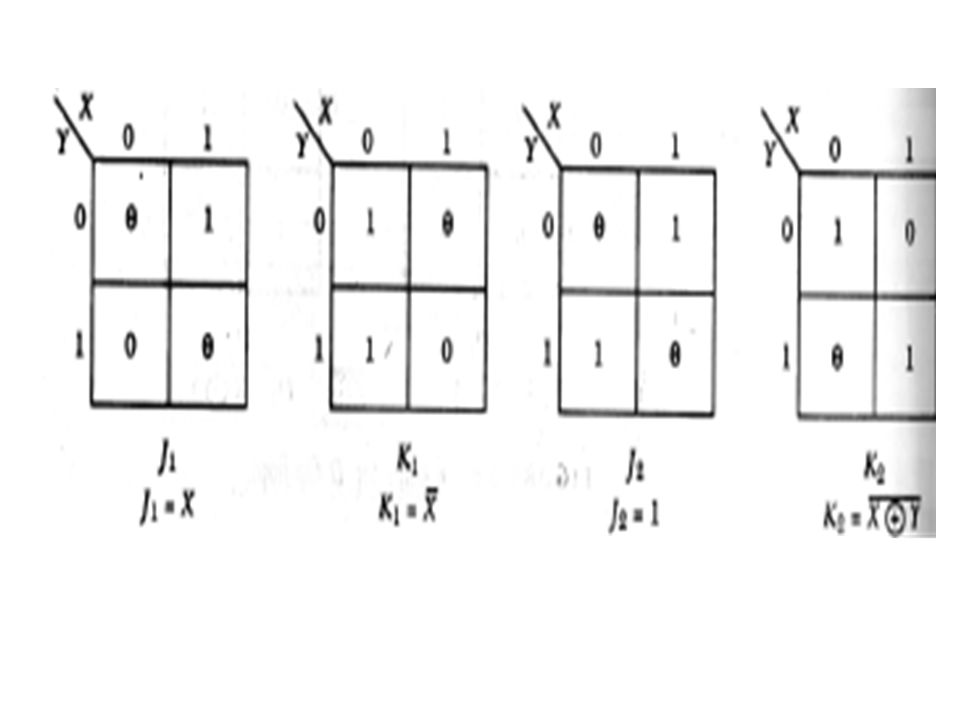
For the given set of inputs and output, design the system using JK flip flop

19
Solution

21
Finite state machine A FSM is an abstract model describing the synchronous sequential machine. FSM design involves drawing state diagram for the problem which is also known as word problem. One state diagram is drawn, the next steps involves reduction, state assignments and its realization or design.

22
Some examples of FSM Positive transition detector i.e. system which gives output 1, whenever the inputs to the system changes from 0 to 1. Vending machine problems Serial Adder Serial Code Converters (BCD to Excess-3) TLC( Traffic Light Controller) Sequence detectors
 TLC( Traffic Light Controller) Sequence detectors.")
23
Positive transition detector
Suppose we have to design a sequential system which is having one serial input IN and will produce output OUT=1 whenever input IN changes from 0 to 1. Input is received one bit per cycle. Step 1: Understand the problem Step 2: Draw state diagram Step3: reduction , state assignments and design

24
Step 1: The system is to have one input line and one output line
Step 1: The system is to have one input line and one output line. Since the possible transitions can 0 to 1 and 1 to 0, so we can assume that we have only two state. Out of these two state one state will represent that current input is 1 and other state will represent current input as 0. Step 2: Draw state diagram

25
Step 3: No reduction needed.
Step 4: State Assignments: Since we have only two states, so we need only one bit to code the two states. In our case lets assign 0 to state Zero and 1 to state One. Step 5: Designs the circuit diagram for this form state table as shown below. Present state QD Input (IN) Next state QD+1 Output (OUT) DA 1 Forming K – Map for DA and OUT we have QD IN 1 QD IN 1 OUT=Q’D.IN DA= IN
 Next state. QD+1. Output (OUT) DA. 1. Forming K – Map for DA and OUT we have. QD. IN. 1. QD. IN. 1. OUT=Q’D.IN DA= IN.")
26
Circuit Diagram:

27
Vending Machine Problem
The vending machine delivers package of gum after receiving minimum of 15 cents of coin. The machine has a single slot that accepts 10 cent coin or 5 cent coin one at a time. A mechanical sensor indicates whether 10 cent coin or 5 cent coin have been inserted.

28
Step 1: Understand problem
Assuming that sensor gives two outputs which sense the coins. Lets take T signal for 10 cent coin and F signal for 5. As per given condition the gum is delivered only when the coin inserted is minimum 15.

29
There is 5 possible best way of getting 15 cent minimum.
> 5 > ( 3 continuous 5 cent coin) > (5 cent follows with 10 cent coin) > (10 cent follows with 5 cent coin) > (2 continuous 10 cent coin) > 5 > 10 (2 continuous 5 cent coin follows with one 10 cent coin)
 2. 5 > 10 (5 cent follows with 10 cent coin) > 5 (10 cent follows with 5 cent coin) > 10 (2 continuous 10 cent coin) 5. 5 > 5 > 10 (2 continuous 5 cent coin follows. with one 10 cent coin)")
30
Since once a package is delivered, the machine should be in initial state for the next customer.
Also T=1 indicates 10 cent coin and F=1 indicates 5 cent coin. We can’t have T=1 and F=1 at a same time. Lets start drawing state diagram.

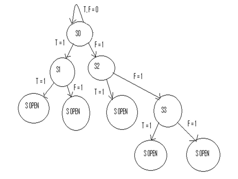
31
Step 2: State Diagram Initially we will start with the state where nothing is being sensed i.e. T=0 and F=0. The system will be in the initial state until T or F is not 1. Once T or F is detected we can start with states. If T=1 means 10 cent coin is being received so this will be indicated by state S1. If initially F=1 means 5 cent coin is received, so we will indicate this as state S2. After S1, if T=1 means (case 4 ) i.e. our condition is satisfied and package will be delivered so it will be indicated by state SOPEN.
 i.e. our condition is satisfied and package will be delivered so it will be indicated by state SOPEN.")
33
Step 3: State Reduction The details techniques for the state reduction will be discussed later. Here we can directly draw the reduced state diagram by care full observations. 5 cent coin follows by 10 cent coin will be having same state when 10 cent coin follows by 5 cent coin. Similarly 10 cent coin state received from starting state is equivalent to two consecutive 5 cent coin.

34
Reduced state diagram

35
State Assignments and design
Present State Q0 Q1 T F Next State Output Z COMMENT 0 0 NO CHANGE 0 1 STATE 01 1 0 STATE 10 X X NOT ALLOW STATE 1 1 1 STATE 11 TO RESET 00

36
FSM for serial adder Suppose we have to add two inputs X and Y where each bits of the inputs are coming serially as shown below

37
State Diagram for serial adder
Since carry generated from first bit addition must be added with the next bits, so care must be taken. Lets we have two states A,B. State A indicating carry=0 and the state B ,indicating carry=1.

38
State table, state assignment
Present state Inputs X Y Next state Output (Sum) A 1 B Present state QN Inputs X Y Next state QN+1 Output (Sum) DQ 1 a. State Table b. State Table after state assignment
 A B. Present state. QN. Inputs. X Y. Next state. QN+1. Output. (Sum) DQ a. State Table. b. State Table after state assignment.")
39
K-Maps and circuit design
K-Map for DQ=XY +XQN+YQN K-Map for sum= XΘYΘQN Where Θ is Exor operation. XY QN 00 01 11 10 1 XY QN 00 01 11 10 1

40
Simplified Presentation

41
Serial code converters
Binary to Gray code converter Gary to binary code converter( self) BCD to Excess-3 code converters ( Home Assignment)
 BCD to Excess-3 code converters ( Home Assignment)")
42
Binary to Gray code converter
In these type of system, input bit stream is coming serially and output is also expected serially. Here we have to use the truth table of converter wisely.

43
1. Whenever MSB is 0 corresponding Gary code value is 0 and when it’s 1 the Gray code is 1.
2. Whenever the second bit, after 0 MSB ,is 0 then the corresponding Gary code is 0 else its 1. 3. Whenever the second bit, after 1 MSB ,is 0 then the corresponding Gary code is 1 else its 0. 4. Whenever the last bit, after 00 ,is 0 then the corresponding Gary code is 0 else its 1. 5. Whenever the last bit, after 01 ,is 0 then the corresponding Gary code is 1 else its 0. 6. Whenever the last bit, after 10 ,is 0 then the corresponding Gary code is 0 else its 1. 7. Whenever the last bit, after 11 ,is 0 then the corresponding Gary code is 1 else its 0. Binary Gray X2 X1 X0 Y2 Y1 Y0 1 2 3 4 5 6 7

44
Draw State diagram using the state table given in the previous slide
Then using the appropriate state assignment and K-Map realization , design the system.

45
Sequence Detector This is special type of systems which is used whenever we need to check a particular pattern in the input sequence Suppose input to the system is serial and we have to design the system such that whenever “101” is detected in the input, output will be 1. INPUT : OUTPUT :

46
There are two types of sequence detector.
(a) overlapping sequence detector (b) non-overlapping sequence detector In (a), we consider the input bit which may be common or overlapping while deciding a pattern or desired sequence in the input bit stream. Let’s take example of sequence detector for 101. If input bit sequence is …. , then output expected is since when fourth bit is received , pattern 101 is received first time and output is available. After that if two bits received are 0 , 1 , then the 1 that is already there while forming pattern of for the first time will again form patter along with the two bit 0 ,1. so output will be 1 again on 6th input bit, i.e the 1 in the 4th location in the input is common in both 101 pattern before and after this 1.
 overlapping sequence detector. (b) non-overlapping sequence detector. In (a), we consider the input bit which may be common or overlapping while deciding a pattern or desired sequence in the input bit stream. Let’s take example of sequence detector for 101. If input bit sequence is …. , then output expected is since when fourth bit is received , pattern 101 is received first time and output is available. After that if two bits received are 0 , 1 , then the 1 that is already there while forming pattern of for the first time will again form patter along with the two bit 0 ,1. so output will be 1 again on 6th input bit, i.e the 1 in the 4th location in the input is common in both 101 pattern before and after this 1.")
47
In (b) we need not to consider the input under overlapping condition ie for obtaining desired sequence, a input bits can not be considered more then once. How to draw state diagram for sequence detector The input to the system is serially. Lets input is X and output is Z. 101, sequence detector means out Z=1 whenever in the input stream X, we have 101 pattern ie for …. , as input stream , then output Z expected is …….

48
Class work : draw state diagram for 1001 sequence detector

49
Non Overlapping Sequence Detector
In non overlapping type of sequence detector, output will be decided once the desired pattern is received and no output will be there for any other pattern. Let draw non-overlapping 101 sequence detector. While drawing state diagram for non overlapping type of system, it’s very easy to draw the state diagram since here each bit is being treated independently as non overlapping. As in the case of 101 detector, for input stream: …… Output will be : …. Chose a pair of three bits and searching for 101. If 101 received then output is 1 otherwise output is zero.

51
EXAMPLE: Draw state diagram for 3 bit palindrome checker i. e
EXAMPLE: Draw state diagram for 3 bit palindrome checker i.e. a system is taking input bit serially and output will be 1 when the three bits form a palindrome sequence.

Similar presentations


>")
>")


 Chapter 5 – Sequential Circuits Part 1 – Storage.>")


 The slides included herein were taken from the.>")


