Download presentation
Presentation is loading. Please wait.

1
Occupancy Sensors for High Bay Lighting Control

2
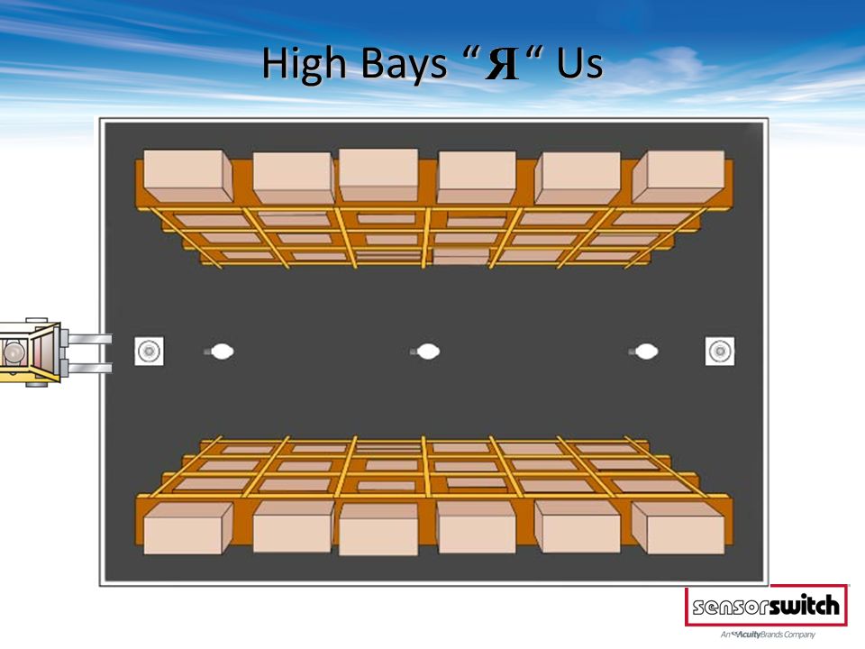
High Bays “ “ Us

4
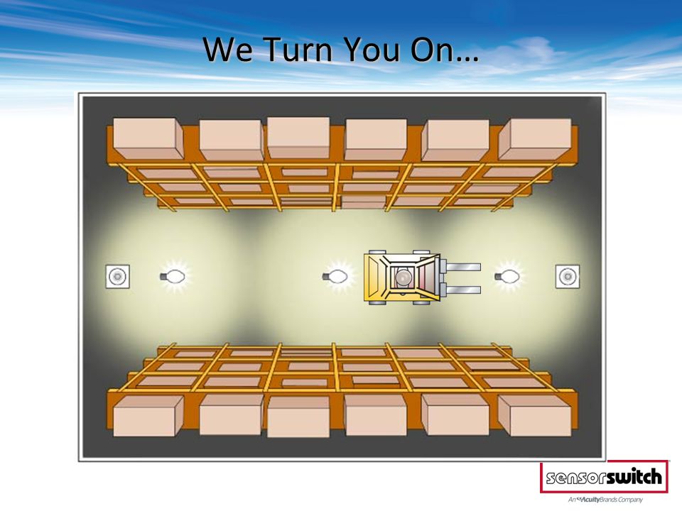
We Turn You On…

6
Then…

7
Then…

8
We Turn You Off

9
In late 1980’s, Sensor Switch was the first company to develop a sensor for Hi/Lo Bi-Level HID applications Since then our product offering has grown to cover applications utilizing many technologies and voltage types: Sensor Switch… the leader in High Bay controls Technologies T-8, T-5 Fluorescent Electronic HID Daylighting Control Voltages 120/277 VAC 347 VAC 208/240 VAC 480 VAC

10
Presentation Outline 1.Coverage Pattern a)360° Circular b)Bi-Directional c)End-of-Aisle 2.Control Schemes a)Total Aisle Control b)Total Aisle Control w/ Lights on Ahead c)Individual Fixture Control d)Individual Fixture Control w/ Lights on Ahead 3.Lighting Types a)T-8, T-5 Fluorescents b)Magnetic HID c)Electronic HID 4.Power Types a)Line Voltage b)Low Voltage 5.Additional Features, Options, & Accessories a)Photocell b)2-Pole c)Low Temp d)Other
360° Circular b)Bi-Directional c)End-of-Aisle 2.Control Schemes a)Total Aisle Control b)Total Aisle Control w/ Lights on Ahead c)Individual Fixture Control d)Individual Fixture Control w/ Lights on Ahead 3.Lighting Types a)T-8, T-5 Fluorescents b)Magnetic HID c)Electronic HID 4.Power Types a)Line Voltage b)Low Voltage 5.Additional Features, Options, & Accessories a)Photocell b)2-Pole c)Low Temp d)Other")
11
High Bay Sensor Basics: Coverage Patterns

12
360° Circular Sensors: SFR 5, CM(R) 6, CM(R)B 6, RM(R) 6, RM(R)B 6, SB(R) 6 Linear End-of-Aisleway Sensors: HM(R) 10, HM(R)B 10 Bi-Directional Center of Aisleway Sensors: HM(R) 50, CM(R)B 50, RM(R) 50 SB(R) 50 High Bay Control Basics: Coverage Types
 6, CM(R)B 6, RM(R) 6, RM(R)B 6, SB(R) 6 Linear End-of-Aisleway Sensors: HM(R) 10, HM(R)B 10 Bi-Directional Center of Aisleway Sensors: HM(R) 50, CM(R)B 50, RM(R) 50 SB(R) 50 High Bay Control Basics: Coverage Types")
13
Mini High-Bay 360° Lens (-5) Recommended for fixtures that have a 1.0 spacing to mounting height ratio or less (e.g. fixtures 30’ on center or less @ a 30’ mounting height). Recommended for mounting heights between 30 to 45 ft (9.14 to 13.72 m) 15 to 20 ft (4.57 to 7.62 m) radial coverage overlaps area lit by a typical high bay fixture Excellent detection of large motion (e.g. walking) up to a 35 ft (10.67 m) Excellent detection of extra large motion (e.g. forklifts) up to a 45 ft (13.72 m) Available in Snap-Fit Enclosure
. Recommended for mounting heights between 30 to 45 ft (9.14 to m) 15 to 20 ft (4.57 to 7.62 m) radial coverage overlaps area lit by a typical high bay fixture Excellent detection of large motion (e.g. walking) up to a 35 ft (10.67 m) Excellent detection of extra large motion (e.g. forklifts) up to a 45 ft (13.72 m) Available in Snap-Fit Enclosure.")
14
Full High Bay 360° Lens (-6) -6: High Bay 360° Lens Best choice for 15 to 45 ft mounting heights 15 to 20 ft. radial coverage overlaps area lit by a typical high bay fixture Large Motion (e.g. walking) detection up to a 35 ft. mounting height Extra Large Motion (e.g. forklifts) detection up to a 45 ft. mounting height Available in Ceiling Mount, Recessed Mount, & two Fixture Mount enclosures
 detection up to a 35 ft. mounting height Extra Large Motion (e.g. forklifts) detection up to a 45 ft. mounting height Available in Ceiling Mount, Recessed Mount, & two Fixture Mount enclosures.")
15
360° High Bay Sensors Snap fits into 2 3/16” H x 1 5/16” W x 1” D opening in any fixture SFR 5 Recess mounts in a 2.65” H x 2.65 W x 1.50” D fixture opening SBR 6

16
360° High Bay Sensors (cont.) Surface mounts to single gang handy box or mounting plate on fixture Mounts through ½ inch knockout on junction box or fixture CMR 6 CMRB 6 Recess mounts in 4” x 4” junction box RMR 6
 Surface mounts to single gang handy box or mounting plate on fixture Mounts through ½ inch knockout on junction box or fixture CMR 6 CMRB 6 Recess mounts in 4 x 4 junction box RMR 6")
17
Bi-Directional Aisleway – Coverage Pattern -50: High Bay Bi-Directional Aisleway Lens Provides 50° bi-directional and 10° wide coverage pattern 1.2 x mounting height equals approximate detection range in either direction. Typical 40 ft. mounting detects 50 ft. in either direction Available in Ceiling Mount, Recessed Mount, & two Fixture Mount enclosures

18
Bi-Directional Aisleway - Sensors Recess mounts in a 2.65” H x 2.65 W x 1.50” D fixture opening SBR 50 Recess mounts in 4” x 4” junction box RMR 50

19
Bi-Directional Aisleway - Sensors (cont.) Mounts through ½ inch knockout on junction box or fixture CMRB 50 Surface mounts to single gang handy box or mounting plate on fixture HMR 50
 Mounts through ½ inch knockout on junction box or fixture CMRB 50 Surface mounts to single gang handy box or mounting plate on fixture HMR 50")
20
Linear End-of-Aisle – Coverage Pattern HM 10: High Bay End-of-Aisle Lens Detects motion from end of aisles up to 110 ft. long Designed to mount 30 ft. high and 10 ft. back from end of aisle

21
HMRB 10 HMR 10 Mounts to single gang handy box Box must rotate to aim sensor Mounts through ½ inch knockout on junction box Sensor rotates for aiming Linear End-of-Aisle- Sensors

22
High Bay Sensor Basics: Control Schemes

23
Entire Aisle Control from Ends High Bay Basics: Control Schemes

24
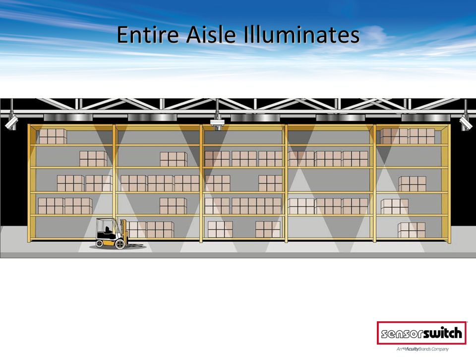
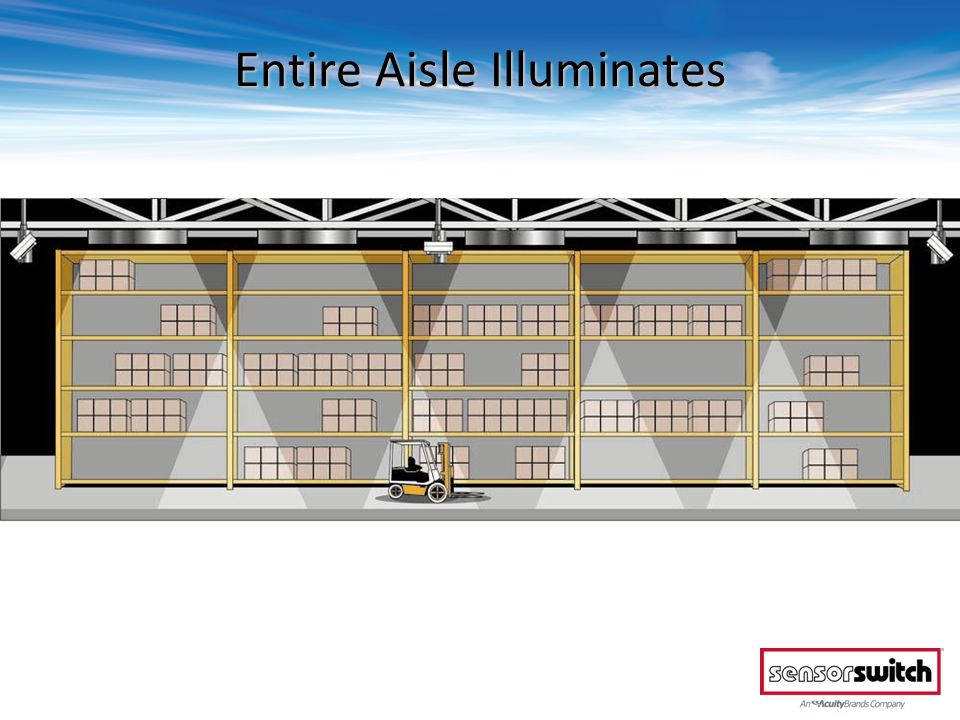
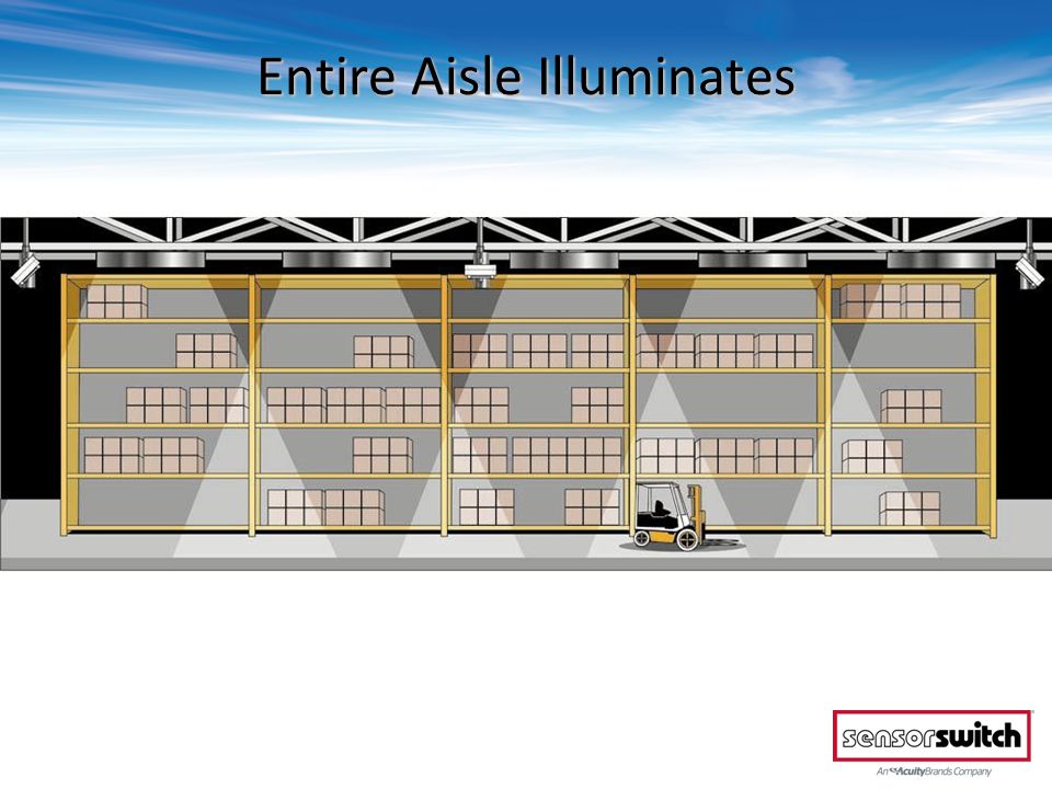
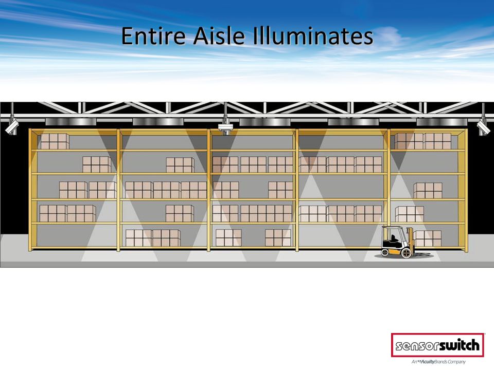
Entire Aisle Control from Ends Use one HMR(B) 10 mounted at each end Linear coverage out to 110 ft. from each end All lights in aisle turn on and off together

25
Entire Aisle Control from Ends High Bay Basics: Control Schemes Entire Aisle Control from Ends & Middle

26
Entire Aisle Control from Ends & Middle Use one HMR(B) 10 mounted at each end Use one or more CMRB 50, RMR 50, or HMR 50s mounted in middle
 10 mounted at each end Use one or more CMRB 50, RMR 50, or HMR 50s mounted in middle")
27
Let’s See How That Works!

28
Forklift Enters Aisle

29
Entire Aisle Illuminates

34
Forklift Leaves Aisle

35
Entire Aisle Turns Off or Dims

36
High Bay Basics: Control Schemes Entire Aisle Control from Ends Entire Aisle Control from Ends & Middle Individual Fixture Control

37
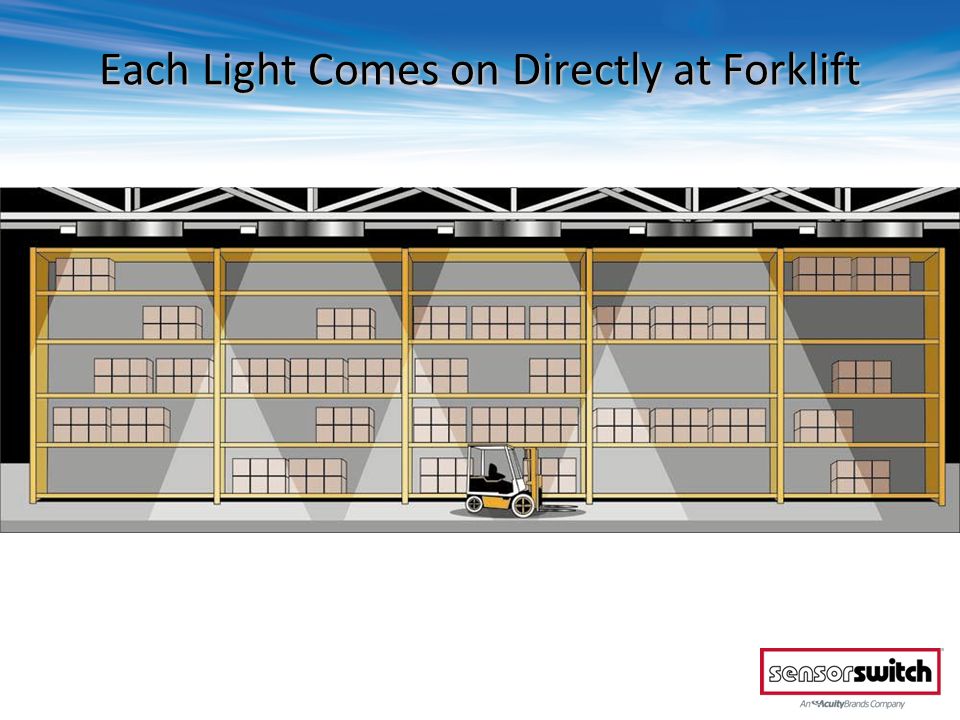
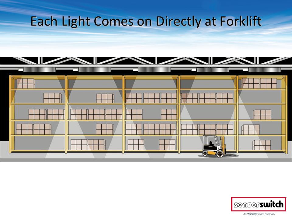
Individual Fixture Control Use a SFR 5, CMR(B) 6, SBR 6, or RMR 6 mounted directly to or adjacent to High Bay fixture Circular coverage pattern matches typical High Bay lighting fixture’s coverage area Typical application with fixtures mounted 40 ft. high Sensors view 20 ft. in both directions Fixtures turn on one at a time -6 Lens Coverage Pattern

38
Let’s See How That Works!

39
Individual Fixture Control

40
Forklift Enters Aisle – First Light Comes On

41
Each Lights Comes on Directly at Forklift

42
Each Light Comes on Directly at Forklift

45
Lights Start Turning Off Behind Forklift

46
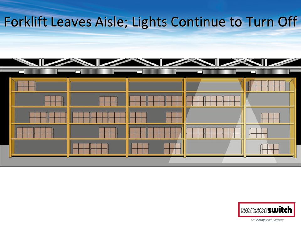
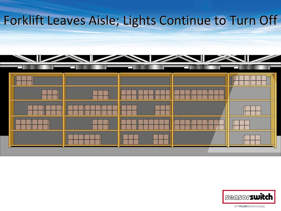
Forklift Leaves Aisle; Lights Continue to Turn Off

49
Lights Finish Turning Off

50
High Bay Basics: Control Schemes Entire Aisle Control from Ends Entire Aisle Control from Ends & Middle Individual Fixture Control Individual Fixture Control w/ Lights On Ahead

51
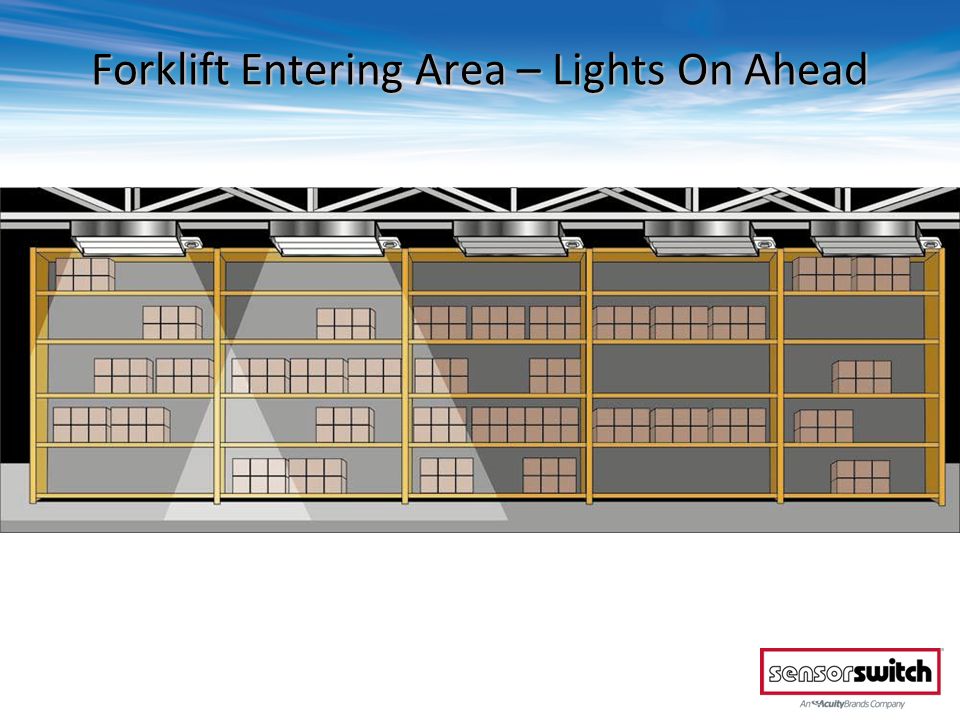
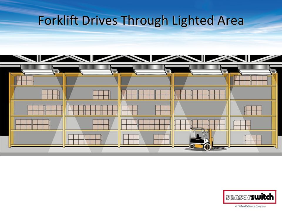
Sensors detect ahead of fixture providing lights ahead of occupant Fixtures turn on one at a time Individual Fixture Control w/ Lights On Ahead

52
Use a CMRB 50, RMR 50, SBR 50,or HMR 50 mounted directly to or adjacent to each High Bay fixture Typical application with fixtures mounted 40 ft. high Sensors view 1.2 x mounting height in both directions Individual Fixture Control w/ Lights On Ahead

53
Let’s See How That Works!

54
Lights Off

55
Forklift Entering Area – Lights On Ahead

57
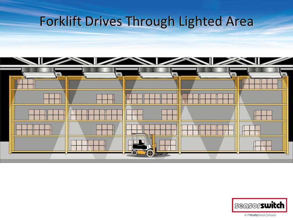
Forklift Enters Lighted Area

58
Forklift Drives Through Lighted Area

61
Forklift Nears End of Aisle

62
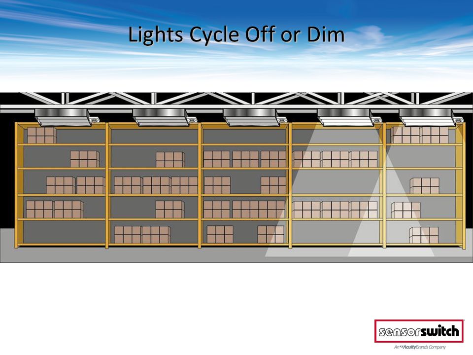
Forklift Exits Aisle – Lights Start to Cycle Off

63
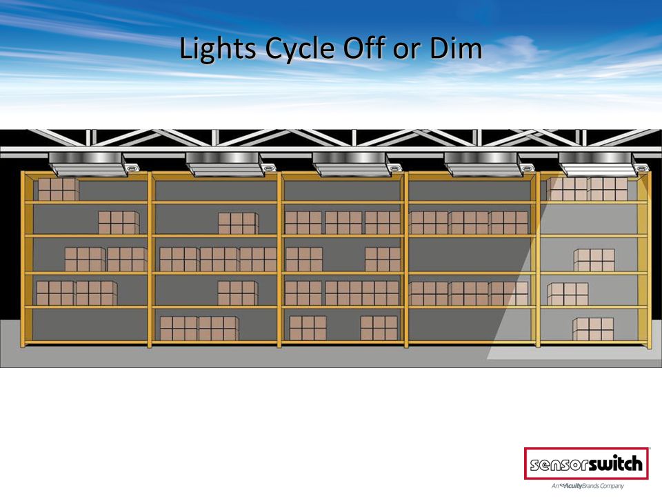
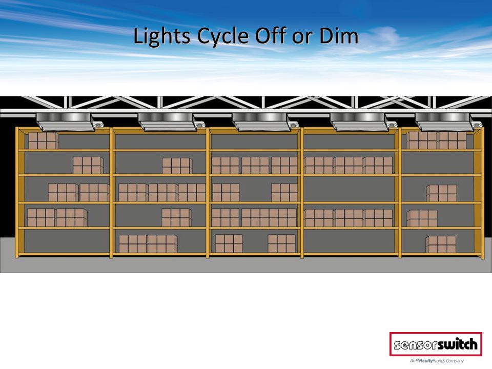
Lights Cycle Off or Dim

67
High Bay Sensor Basics: Lighting Types

68
High Bay Control Basics: Lighting Types T-8 & T-5 Fluorescent Lighting Magnetic HID Bi-Level Lighting Electronic HID Lighting LED

69
High Bay Sensor Basics: Power Types

70
208/240 VAC High Bay Control Basics: Power Types 120/277 VAC – Standard Line Voltage Sensors 347 VAC – Available with “-3” option 480 VAC

71
CMR 6 480/ CMR 6 208 CMRB 6 480 / CMRB 6 208 CMRB 50 480 / CMRB 50 208 HMRB 10 480 / HMRB 10 208 Sensors for 480 or 208/240 VAC

72
SBR 6 480 / SBR 6 208 SBR 50 480 / SBR 50 208 Sensors for 480 or 208/240 VAC (cont.) RMR 6 480 / RMR 6 208 RMR 50 480 / RMR 50 208
 RMR / RMR RMR / RMR")
73
What about Low Voltage?

74
CM 6 CMB 6 CMB 50 HMB 10 Low Voltage High Bay Sensors HM 50 HM 10 Available with same enclosures and lenses as line voltage sensors

75
Low Voltage High Bay Sensors (cont.) RM 6 RM 50 SB 6 SB 50 Available with same enclosures and lenses as line voltage sensors
 RM 6 RM 50 SB 6 SB 50 Available with same enclosures and lenses as line voltage sensors")
76
Why Low Voltage for High Bay Control? Line Voltage sensors are rated for 5 Amps Power Packs are rated for 20 Amps

77
PP 20 SH Can Low Voltage be used w/ HID? The PP 20 SH power pack enables any low voltage sensor to be used to control magnetic HID lighting Relay in power pack switches relays in fixtures Start-to-High Timer is built into Power Pack

78
CM 6 Mount Sensors on 40’ Grid Pattern Power Pack Low Voltage High Bay Application – Open Areas

79
Area empty: lights are Dim or Off Low Voltage High Bay Application – Open Areas Mount Sensors on 40’ Grid Pattern

80
Someone enters Area empty: lights are Dim or Off Mount Sensors on 40’ Grid Pattern Low Voltage High Bay Application – Open Areas

81
Lights turn on Mount Sensors on 40’ Grid Pattern Someone enters Low Voltage High Bay Application – Open Areas

82
What About Photocell Options?

83
Photocell views up through rear of Fixture Mount (Box) sensors with –P option. Sensors: CM(R)B 6 P, CM(R)B 50 P Photocell views down through lens of Ceiling, SB, and Recessed Mount sensors with –P option. Sensors: CM(R) 6 P, RM(R) 6 P, SB(R) 6 P Photocell views down through lens of Fixture Mount sensors with –PD option. Sensors: CM(R)B 6 PD On-Off Photocell Options
B 6 P, CM(R)B 50 P Photocell views down through lens of Ceiling, SB, and Recessed Mount sensors with –P option. Sensors: CM(R) 6 P, RM(R) 6 P, SB(R) 6 P Photocell views down through lens of Fixture Mount sensors with –PD option. Sensors: CM(R)B 6 PD On-Off Photocell Options.")
84
What Else?

85
High / Low Dimming from Occupancy The Dimming Option (D) provides a 0-10 VDC dimming output for controlling a dimmable fluorescent or electronic HID ballast Sensor has “Idle time before Dim” setting Once expired, dimming output drops to full dim If “Dim to Off” time delay also expires, sensors internal relay will open If fixture doesn’t need to ever go off, leave relay wires unconnected
 provides a 0-10 VDC dimming output for controlling a dimmable fluorescent or electronic HID ballast Sensor has Idle time before Dim setting Once expired, dimming output drops to full dim If Dim to Off time delay also expires, sensors internal relay will open If fixture doesn’t need to ever go off, leave relay wires unconnected")
86
CMR 6 2P CMRB 6 2P CMRB 50 2P HMRB 10 2P 2-Pole High Bay Sensors Ideal for Inboard / Outboard control

87
2-Pole High Bay Sensors (cont.) RMR 6 2P RMR 50 2P Ideal for Inboard / Outboard control SBR 6 2P SBR 50 2P
 RMR 6 2P RMR 50 2P Ideal for Inboard / Outboard control SBR 6 2P SBR 50 2P")
88
Available option on all sensors (LT) Operational Temperature Down to -40 Degrees C/F Perfect for Cold Storage applications Low Temp “LT” Option
 Operational Temperature Down to -40 Degrees C/F Perfect for Cold Storage applications Low Temp LT Option")
89
Cold Storage Applications In applications such as walk-in coolers it is beneficial to keep lamps warms. Optional operational schemes within our 2 Pole High Bay sensors enable some lights to be turn off while some constantly stay on to keep lights warm Alternating Off (AO): One pole shuts off during first period of no occupancy then second pole shuts off during next period of no occupancy.
: One pole shuts off during first period of no occupancy then second pole shuts off during next period of no occupancy..")
90
Programmable Functions Time Delay Photocell Settings 100 Hour burn-in timer Dim levels (-D) Additional Sensor Features All Fixture and Recessed Mount sensors have a microcontroller & are push-button programmable
 Additional Sensor Features All Fixture and Recessed Mount sensors have a microcontroller & are push-button programmable")
91
Lens Turret Rotates 90 Degrees Enables proper alignment regardless of aisle direction CMRB 50 / RMR 50 Lens Turret

92
Sensors may be masked for end of aisle Masking Sensors

93
Sensors may also be masked for center of aisle

94
FB 3 Bracket for Fixture Mount Sensors Shallow fixtures may partially block sensor view Using the FB 3 Fixture Bracket allows sensor to be mounted level with bottom of fixture allowing total view

95
Questions? © 2013 Sensor Switch

Similar presentations


 range *Selectable.>")


