Download presentation
Presentation is loading. Please wait.

1
CEE 498C AutoCAD Graphics Communication for Civil and Environmental Engineers Creating Drawings Sets for CEE Projects Chapter 18

2
“ The United States National CAD Standard (NCS) streamlines and simplifies the exchange of building design and construction data from project development throughout the life of a facility. It coordinates the efforts of the entire industry by classifying electronic building design data consistently allowing streamlined communication among owners and design and construction project teams. Use of the NCS can reduce costs and produce greater efficiency in the design and construction process National CAD Standards for Creating Drawing Sets

3
NCS and Consistency common terms and symbols naming conventions Information in the same place in all drawing sets predictable file translation Streamline checking errors and omissions. http://www.nationalcadstandard.org National CAD Standards for Creating Drawing Sets

4
NCS and BIM NCS is connected with the National BIM Standard- United States (NBIMS-US). NCS supports the printed output of NBIMS Clients requesting NCS compliance?

5
First release in July 1999 The United States National CAD Standard® (NCS) is comprised of: –American Institute of Architect's (AIA) CAD Layer Guidelines –the Construction Specification Institute's (CSI) Uniform Drawing System (UDS) – the National Institute of Building Sciences (NIBS) Plotting Guidelines. National CAD Standards for Creating Drawing Sets

6
–Excel spreadsheets containing AIA CAD Layer Guideline files, UDS Terms and Abbreviations, Schedules and Regulatory Information, and Plotting Guidelines tables –DWG symbols files National CAD Standards for Creating Drawing Sets

7
Who Does What? CAD Layer Guidelines (AIA): –list of layers that may be included –Format for naming layers in CAD Plotting Guidelines (NIBS) –Color in AutoCAD file, plotted line width & plotted color
: –list of layers that may be included –Format for naming layers in CAD Plotting Guidelines (NIBS) –Color in AutoCAD file, plotted line width & plotted color.")
8
The Construction Specification Institute –Drawing set organization –Drawing sheet organization –Schedule organization –Drafting conventions –Terms and Abbreviations –Symbols –Notations National CAD Standards for Creating Drawing Sets

9
Drawing Set Organization Components of a CEE drawing set

10
Family of Construction Drawings

11
Drawing Set Hierarchy O - OPERATIONS Z - CONTRACTOR/SHOP DRAWINGS X - OTHER DISCIPLINES R - RESOURCE T - TELECOMMUNICATIONS E - ELECTRICAL M - MECHANICAL D - PROCESS P - PLUMBING F - FIRE PROTECTION Q - EQUIPMENT I - INTERIORS A - ARCHITECTURAL S - STRUCTURAL L - LANDSCAPE W – CIVIL WORKS C – CIVIL B – GEOTECHNICAL V – SURVEY/MAPPING H – HAZARDOUS MATERIALS G - GENERAL Cover Sheet

12
The title page for the set of the drawings. Includes some or all of the following: Title of the project Project Number Location map Name of the owner Names, signatures, and stamps of designers Index Legend Survey data Additional Information

13
Cover Sheet

14
(G) General information sheet/s –(G) sheets –Include information about site location and data –Abbreviations –Building Code (v) Survey Sheets V sheets, include details about surveying data and maps
 General information sheet/s –(G) sheets –Include information about site location and data –Abbreviations –Building Code (v) Survey Sheets V sheets, include details about surveying data and maps")
17
(G) Geotechnical (Soil) Sheets (L) Landscape drawings (S) Structural Drawings –provide information for designing, fabricating, manufacturing, and erecting the structural elements
 Geotechnical (Soil) Sheets (L) Landscape drawings (S) Structural Drawings –provide information for designing, fabricating, manufacturing, and erecting the structural elements")
18
Multiple Views – The CEE Perspective ""

19
""

20
""

21
Section Views – The CEE Perspective ""

22
Drawing Structural Steel Components

23
Drawing RC Structural Components

24
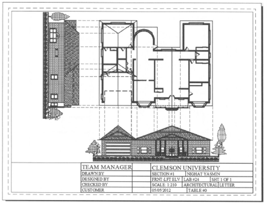
(A) Architectural Drawings Floor plans: horizontal orthographic views Site Plan: horizontal orthographic views Elevations: vertical orthographic views, front- rear-left- and right. May also be NSWE. Sectional views: internal views

27
Elevation

35
(F) Fire Protection drawings (P) Pluming drawings Information about the site and the structure; about drain waste, hot and cold water supply, and fixture information (M) Mechanical (E) Electrical (T) Telecommunication
 Fire Protection drawings (P) Pluming drawings Information about the site and the structure; about drain waste, hot and cold water supply, and fixture information (M) Mechanical (E) Electrical (T) Telecommunication")
36
(PnP) Plan and Profile Drawings Water and sewer pipelines. Storm drainage system Curbs Sidewalks Road Constructions

37
Drawing Roads

41
Sheet Organization

42
Paper Size ANSI

43
Sizeinchesmillimeters Letter8.5 × 11216 × 279 Legal8.5 × 14216 × 356 Tabloid11 × 17279 × 432 Ledger17 × 11432 × 279 Paper Sizes ISO ANSI Sizeinchesmillimeters ANSI A8.5 × 11216 × 279 ANSI B11 × 17279 × 432 ANSI C17 × 22432 × 559 ANSI D22 × 34559 × 864 ANSI E34 × 44864 × 1118

44
Paper Sizes International ISO 216 A-Series Paper Sizes Sizeinchesmillimeters A033.1 × 46.8841 × 1189 A123.4 × 33.1594 × 841 A216.5 × 23.4420 × 594 A311.7 × 16.5297 × 420 A48.3 × 11.7210 × 297 A55.8 × 8.3148 × 210 A64.1 × 5.8105 × 148 A72.9 × 4.174 × 105 A82.0 × 2.952 × 74 A91.5 × 2.037 × 52 A101.0 × 1.526 × 37

45
Paper Size ISO

46
Standard Sheet Identification –discipline designator –sheet type designator –sheet sequence number –user-defined designator A A N N N U U U Discipline Designators A A N N N U U U Sheet Type Designator A A N N N U U U Sheet Sequence Number A A N N N U U U User-Defined Designator A = alphabetical character N = numerical character U = user-defined

47
Sheet Org.: Discipline Designator A - N N N Level 1 designator Optional Level 2 designator / modifier

48
National Cad Standard V5 Discipline Designators

50
DesignatorNameAdditional Description Cover Sheet GGeneral Sheet list, symbols, code summary, etc. H Hazardous Materials Abatement, handling, etc. V Survey / Mapping BGeotechnical CCivil LLandscape SStructural AArchitectural IInteriors Level 1 Discipline Designator

51
DesignatorNameAdditional Description QEquipment FFire Protection PPlumbing DProcess MMechanical EElectrical T Telecommunicati ons RResourceExisting conditions / buildings XOther Disciplines Z Contractor / Shop Drawings OOperations Level 1 Discipline Designator

52
National Cad Standard V5 Discipline Designators A A N N N LEVEL 2 Optional Architectural Modifiers

53
Sheet Org.: Sheet Type Designator A A N N N 0 General (symbols legend, notes, etc.) 1 Plans (horizontal views) 2 Elevations (vertical views) 3 Sections (sectional views) 4 Large Scale Views (plans, elevations, sections) 5 Details 6 Schedules and Diagrams 7 User Defined 8 User Defined 9 3D Representations (isometrics, perspectives, photographs)
 1 Plans (horizontal views) 2 Elevations (vertical views) 3 Sections (sectional views) 4 Large Scale Views (plans, elevations, sections) 5 Details 6 Schedules and Diagrams 7 User Defined 8 User Defined 9 3D Representations (isometrics, perspectives, photographs)")
54
Sheet Org.: Sheet Sequence Number A A N N N The sheet sequence number identifies each sheet in a series of the same discipline and sheet type. The first sheet of each series is numbered 01, followed by 02 through 99.

55
Sheet Org.: User-Defined Designators A A N N N U U UExamples - Supplemental Drawings

56
A supplemental drawing is issued when the entire drawing must be altered and reissued for supplementary work involving a change in scope. The following user defined suffix characters are used: X Complete Changes R Revised Issues of similar scope A,B,C,.. PHASED WORK WHERE MULTIPLE VERSIONS ARE `EXPECTED Sheet Org.: User-Defined Designators

57
Sample Typical Drawing Set Sheet Sheet Title G-001 Cover Sheet A-001 Notes and Symbols A-101 Floor Plan A-102 Reflected Ceiling Plan A-103Roof Plan A-201 Exterior Elevations A-301 Building Sections A-302 Wall Sections A-401 Enlarged Toilet Plan A-501 Details A-601 Room Finish Schedule A-602 Door & Window Schedules UDS establishes organization and provides consistency among disciplines. Thus, a floor plan may be located and identified as: S - 101 Structural First Floor Plan A - 101 Architectural First Floor Plan M - 101 Mechanical First Floor Plan E - 101 Electrical First Floor Plan Drawing Set Consistency

58
CAD Layer Guidelines

59
AIA CAD Layer Guidelines AI-WALL-FULL-DIMS-N Discipline Designator Major Group Minor Group 1 Minor Group 2 Status

60
CAD Layer Name: Discipline Designator AI-WALL-FULL-DIMS-N AA - Level 1 Discipline Designator G GeneralF Fire Protection H Hazardous MaterialsP Plumbing V Survey/MappingD Process B GeotechnicalM Mechanical W Civil WorksE Electrical C CivilT Telecommunications L LandscapeR Resources S Structural X Other Disciplines A ArchitecturalZ Contractor / Shop Drawings I InteriorO Operations Q Equipment AA - Level 2 - modifier character Designator Description Content A Architectural Any or all AS Architectural Site Site Plan AD Architectural Demo. Protection & Removal AI Architectural Interiors Interior Finishes As for Drawing Numbering

61
CAD Layer Name: Major Group AI-WALL-FULL-DIMS-N The mandatory Major Group field is a four-character field that identifies a major building system. The prescribed Major Group field codes (four-character abbreviations) show on the Layer List are logically grouped with specific discipline designators. However, any Major Group may be combined with any prescribed Discipline Designator, provided that the definition of the Major Group remains unchanged. User-defined Major Group field codes are not permitted.
 show on the Layer List are logically grouped with specific discipline designators. However, any Major Group may be combined with any prescribed Discipline Designator, provided that the definition of the Major Group remains unchanged. User-defined Major Group field codes are not permitted..")
62
Examples: V* - BLDG - *Surveying / mapping – buildings and primary structures V* - POWR - *Surveying / mapping – power B* - BORE - *Geotechnical - borings C* - DRIV - *Civil – driveways S* - BEAM - *Structural – beams S* - FNDN - *Structural – foundations A* - DOOR - *Architectural – doors AI – WALL - * Architectural Interior – walls CAD Layer Name: Major Group

63
CAD Layer Name: Minor Groups AI-WALL-FULL-DIMS-N The optional Minor Group fields are four-character fields that provide further clarification of information contained on a layer. The prescribed Minor Group field codes (four-character abbreviations) show on the Layer List are logically grouped with specific discipline designators. However, any Major Group may be combined with any prescribed Discipline Designator, provided that the definition of the Major Group remains unchanged. User-defined Minor Group field codes are permitted.
 show on the Layer List are logically grouped with specific discipline designators. However, any Major Group may be combined with any prescribed Discipline Designator, provided that the definition of the Major Group remains unchanged. User-defined Minor Group field codes are permitted..")
64
Examples: V* - BLDG - DECK Surveying / mapping – buildings - outdoor decks V* - POWR - MHOL Surveying / mapping – power - manholes B* - BORE - FDTA Geotechnical – borings – field data C* - DRIV - FLNE - SIGNCivil – driveways – fire lane – pavement markings S* - BEAM - STEL Structural – beams - steel S* - FNDN - PIER Structural – foundations – drilled piers A* - DOOR - FULL Architectural – doors – full height AI – WALL - FIRE Architectural Interior – walls – fire wall CAD Layer Name: Minor Groups

65
CAD Layer Name: Status AI-WALL-FULL-DIMS-N The optional Status field is a one-character field that distinguishes the data contained on the layer according to the status of the work or the construction phase. The prescribed field codes are as follows: NNew work EExisting to remain DExisting to demolish FFuture work TTemporary work MItems to be moved XNot in contract 1-9Phase numbers

66
Organizing Drawing Information

67
Structure for identifying spaces, objects, components Reference Symbols Notes –General –Reference Keynotes –Sheet Keynotes

68
Identifying Spaces, Objects Components

69
Reference Symbols

70
Reference Symbols: Examples from Skilling Ward Magnusson Barkshire Inc. Detail Plan Number Identification Sheet Number Key Plan Indicator Letter denotes Building Section or Elevation Revision Indicator cloud area of revision Remark Indicator G – General Notes D – Demolition Notes R – Remodel Notes S – Site Notes Existing Building Grid New Building Grid Detail Letter Identification Sheet Number Wall Section Letter Identification Sheet Number Building Section Letter Identification Sheet Number Building Elevation Letter Identification Sheet Number

71
Notes Example: A02-04.dwg

72
General Notes To provide information applicable to the entire set of construction drawings. Should be located in the G series drawings; however, each discipline may have their own General Notes Located in the 0-numbered sheets for each discipline set. For Example: "Dimensions where shown are to face of concrete, masonry, or stud”

73
Reference Keynotes: Masterformat for specifications (CSI) DivisionSpecificationDivisionSpecification 1General Req.9Finishes 2Sitework10Specialties 3Concrete11Equipment 4Masonry12Furnishings 5Metals13Special Construction 6Wood and Plastics14Conveying Systems 7Thermal and Moisture Protection15Mechanical 8Doors and Windows16Electrical
 DivisionSpecificationDivisionSpecification 1General Req.9Finishes 2Sitework10Specialties 3Concrete11Equipment 4Masonry12Furnishings 5Metals13Special Construction 6Wood and Plastics14Conveying Systems 7Thermal and Moisture Protection15Mechanical 8Doors and Windows16Electrical")
74
Reference Keynotes: Masterformat for specifications (CSI)
")
75
Reference Keynotes

76
Sheet Keynotes

77
Example: Roosevelt Commons

Similar presentations


Their layout and format. 2)The terms and definitions used and their legal ramifications.>")


