Download presentation
Presentation is loading. Please wait.

1
4/15/2017 7:34 AM Fire Sprinkler Systems Prepared by Thomas Bartsch Chief Fire Inspector (ret) Former Chief of Department, Valley Stream, NY © 2007 Microsoft Corporation. All rights reserved. Microsoft, Windows, Windows Vista and other product names are or may be registered trademarks and/or trademarks in the U.S. and/or other countries. The information herein is for informational purposes only and represents the current view of Microsoft Corporation as of the date of this presentation. Because Microsoft must respond to changing market conditions, it should not be interpreted to be a commitment on the part of Microsoft, and Microsoft cannot guarantee the accuracy of any information provided after the date of this presentation. MICROSOFT MAKES NO WARRANTIES, EXPRESS, IMPLIED OR STATUTORY, AS TO THE INFORMATION IN THIS PRESENTATION.

2
What is a Sprinkler System
A fire sprinkler system is an ACTIVE fire protection measure, consisting of a water supply system, providing adequate pressure and flow of water through a distribution piping system, onto which fire sprinklers are connected, Sprinkler systems have been around since the late 1880’s, In 1874, H.S. Pamelee patented the first practical automatic sprinkler,

3
Life Safety Considerations
No reported multiple deaths in a completely sprinkled building, Life Safety is enhanced, Combustion products are limited, with extinguishment in the incipient stage, Controls 70% of all fires with five or fewer sprinklers activated.

4
The Codes

5
The Codes By code definition, there are TWO categories of fire suppression systems; Required Systems Non-Required Systems Required Systems are those required to be installed, by code, due to life safety and/or building contents, Non-Required Systems are installed systems not required by the code,

6
The Codes It is unlawful to occupy any portion of a building until the REQUIRED suppression system has been tested and approved, When a REQUIRED system is out of service, and where required by code enforcement, the building shall evacuated or an approved Fire Watch shall be provided, whose only duty is to patrol the premises and keep watch for fires, The Fire Watch must have means to notify the FD.

7
Sprinkler Design

8
Pipe Schedule or Hydraulically Calculated.
Design There are two ways to design a sprinkler system; Pipe Schedule or Hydraulically Calculated. Pipe Schedule: pipe is sized according to systems pressure and required flow, sprinkler discharge density and estimated area of coverage determine pipe size, Hydraulic Calculated: an engineered approach to match fire hazard to potential water supply pressure and volume, most automatic sprinklers today are hydraulically calculated,

9
NFPA 13 requires hydraulically designed systems to have a secured sign placed at the valve supplying designed area. This in addition to the “General Information” sign,

10
Design NFPA Standard 13, “Standard for the Installation of Sprinkler Systems”, now requires, on new systems, a permanent marked and secured “General Information Sign”, While sign is helpful, it should not be considered a complete hazard assessment of the building or system.

11
Sample of “General Information Sign” required by NFPA 13 on new systems

12
Types of Systems

13
Types of Systems There are four major types of sprinkler systems;
The Wet Pipe system, The Dry Pipe system, The Deluge system and The Pre-Action system.

14
Types of Systems Wet pipe --------- by far the most common,
Dry-pipe where water freezing is possible, Deluge for high hazard applications, Pre-Action where concerns over water damage.

15
Wet Pipe Sprinkler

16
Wet Pipe Sprinkler Pipes are always filled with water. Heat from fire opens a sprinkler head, Usually only one or two heads open, Water flows until it is shut off, The open sprinkler head(s) is replaced and the system is reset.
 is replaced and the system is reset.")
17
An opening sprinkler head triggers the system

18
Wet Pipe Sprinkler A one-way clapper prevents water from re-entering the water supply, Gauges on both sides of the main valve, register pressure on the supply and system sides, A retard chamber prevents sudden pressure surges which could cause a false alarm, An alarm check valve detects water flow and activates the alarm system,

19
Wet Pipe Sprinkler There is a control valve to shut off the system, normally an O.S.& Y. (Outside Stem and Yoke) or (Outside Screw and Yoke), There is a main drain valve which drains the system for service, And an Inspectors Test Valve, usually at the end of the system, used to simulate flow from a single head and to measure the system response,

20
Typical wet pipe sprinkler valve
Clapper Valve

21
Wet Pipe Sprinkler Restoration of the System, Liability Issues;
Some occupancies have required systems for life safety, i.e., public assembly, hotels and high-rises, Does your FD allow restoration of the system? If Not, then require a FIRE WATCH or EVACUATE THE BUILDING….. Or at least, shut off the closest control valve and leave the rest of the system operational,

22
Wet Pipe Sprinkler If your SOP allows restoration;
after the fire is completely under control, the closest sectional water control valve should be closed, the main control valve should not be closed unless there are no sectional valves,

23
Wet Pipe Sprinkler Restoration of the System;
shut down any water source supplying the system, the sprinkler head(s) are replaced with an identical one from the spares in the sprinkler control room, re-open any closed control valves, open the Inspectors Test Valve to ensure water is flowing to the topmost sprinkler.
 are replaced with an identical one from the spares in the sprinkler control room, re-open any closed control valves, open the Inspectors Test Valve to ensure water is flowing to the topmost sprinkler.")
24
Wet Pipe Sprinkler System

25
Dry Pipe Sprinkler

26
Dry Pipe Sprinkler Dry pipes systems are used in unheated buildings, but the valve room must be heated, Dry pipe systems are more difficult to design than wet pipe systems and are harder to restore,

27
Dry Pipe Sprinkler Pipes are not filled with water (but with pressurized gas or air), Heat from a fire opens a sprinkler head, Usually only one or two heads open, Air pressure drops in the piping and opens a water valve (the dry-pipe valve),
,")
28
Dry Pipe Sprinkler Water fills the pipes and exits through an open sprinkler head(s), Water flows until shut off, Open sprinkler head is replaced, System is reset,

29
Pipes in protected space are filled with air or inert gas; an opening sprinkler head, triggers the system by releasing the air or gas, which allows water to flow into the pipes and then out through the open sprinkler head,

30
Dry Pipe Sprinkler A dry pipe valve keeps pressurized air above the supply water pressure, The clapper valve has a locking mechanism to keep the clapper open until it is reset, by draining the system, opening the dry pipe valve cover and resetting the lock, Dry pipe systems are a little slower to activate than wet pipe systems, so most have either an Exhauster or Accelerator to speed up the system operation,

31
Typical Dry Pipe Valve

32
Dry Pipe Sprinkler The Exhauster detects decrease in air pressure and helps bleed off air,

33
Dry Pipe Sprinkler The Accelerator detects decrease in air pressure and pipes air pressure below the clapper valve, to speed up it’s opening,

34
Typical Dry Pipe Sprinkler set up

35
Dry Pipe Sprinkler Restoration of the System;
resetting is not usually performed by FD personnel, notify the property owners that the system has activated, the system has to be drained and the dry pipe valve has to be reset, this is a complex procedure, in mild weather, the system can stay in a wet condition.

36
Deluge System

37
Deluge Sprinkler Pipes are not filled with water (or gas),
All sprinkler heads are pre-opened, A signal from a detection device mechanically opens a water valve, water fills the pipes and flows from all heads, water flows until shut off, system is reset.

38
Deluge Sprinkler Primarily installed in special hazard areas that have fast spreading fire, ( i.e. petroleum facilities, hazardous materials), Are also used to apply protein and AFFF foams, Activation will cause great quantities of water or foam to flow, Usually requires several detectors to activate before discharging.

39
Pipes in protected area are empty; a detector signal triggers the system, allowing water/foam to enter pipes and flow from all sprinkler heads (which are already open),
,")
40
Deluge System Restoration of the System;
the deluge clapper valve must be manually reset with the latching mechanism in place, the detection system is re-activated, because of these procedures, it is not recommended for the FD to restore the system, leave it to the professionals.

41
Pre-Action System

42
Pre-Action Sprinkler Pipes are not filled with water,
All sprinkler heads are of the standard type (they are closed), A detection device opens a water valve, Water fills the pipes, Water only flows from a sprinkler head if it is opened by heat from a fire, Water flows until shut off and system is reset.
, A detection device opens a water valve, Water fills the pipes, Water only flows from a sprinkler head if it is opened by heat from a fire, Water flows until shut off and system is reset.")
43
Pre-Action Sprinkler Used primarily to protect property where water could severely damage facilities or equipment, (historical items) Similar to dry-pipe and deluge system; closed piping, little or no air/gas pressure, water does not flow to the sprinkler heads until detector activates, water on fire after sprinkler head fuses, Turns into a wet system, but allows personnel to check/fight fire before head fuses,

44
Pipes in protected area are empty; a detector signal triggers the system, allowing water to enter pipes and flow into piping network; heat from a fire may then open a sprinkler head; accidental damage to a head will not result in water flow,

45
Pre-Action Sprinkler Restoration of the System;
the deluge clapper valve must be manually reset with the latching mechanism in place, the detection system, with supervisory features is re-activated, because of these procedures, it is not recommended for the FD to restore the system, leave it to the professionals.

46
Sprinkler Heads

47
Sprinkler Heads Sprinkler heads are the key components of the system,
Heads must be suitable in design, performance, application and temperature for type of property it is protecting, Standard heads are marked with SSU (standard sprinkler upright) or SSP (standard sprinkler pendent) on the deflector, Side wall heads may be pendent, upright, or horizontal,
 or SSP (standard sprinkler pendent) on the deflector, Side wall heads may be pendent, upright, or horizontal,")
48
Sprinkler Heads frangible bulb fusible link The typical sprinkler head is activated by heat (temperature), opens when a triggering action occurs, a frangible bulb breaks (color indicates temperature setting), a fusible link melts, water flows when head is opened, water is manually shut off, once activated, head must be replace,
, a fusible link melts, water flows when head is opened, water is manually shut off, once activated, head must be replace,")
49
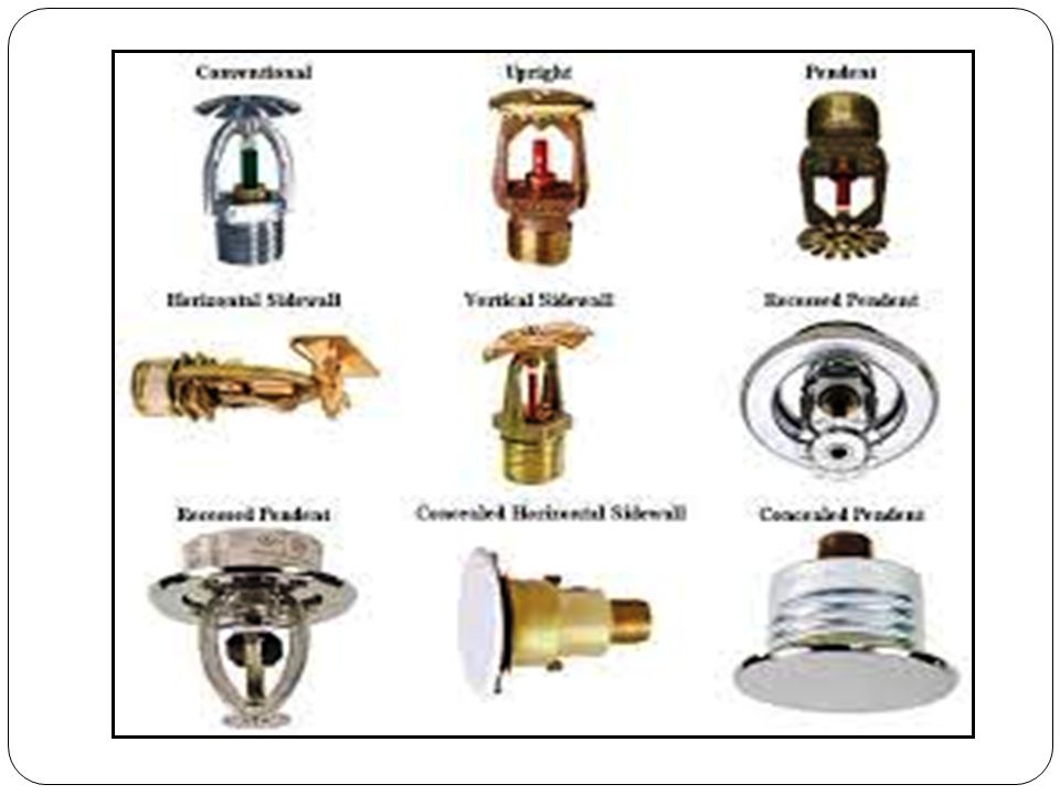
Sprinkler Heads Types; Upright Pendant Sidewall Recessed heads

50
Sprinkler Head Temperature Ratings, Classifications and Color Coding
Temperature Classification Color Coding Glass Bulb Colors F C 57-77 Ordinary Uncolored or Black Orange or Red 79-107 Intermediate White Yellow or Green High Blue Extra High Red Purple Very Extra High Green Black Ultra High Orange 625 343

51
Sprinkler Head Parts

52
Fused Sprinkler Head

53
Frangible Bulb Head

55
frangible bulb

56
fusible link

57
Chemical pellet

58
Recessed (flush)
")
59
Sprinkler Heads Storage Cabinet; extra heads sprinkler wrench
Cabinets hold a minimum of six sprinklers and sprinkler wrench in accordance with NFPA® 13. Less than 300 heads min 6 spares 300 – 1,000 heads min 12 spares More than 1000 heads min 24 spares

60
Control Valves

61
OS&Y secured in open position by chain & lock
Control Valves OS&Y Valve Post Indicator Valve (PIV) Post Indicator Valve Assembly (PIVA) Operating Valves OS&Y secured in open position by chain & lock Supervised control
 Post Indicator Valve Assembly (PIVA) Operating Valves. OS&Y secured in open position by chain & lock. Supervised control.")
62
Outside Screw and Yoke (OS&Y) Valve
Monitored Post Indicator Valve (PIV)
")
63
Post Indicator Valve Assembly (PIVA)
Wall Post Indicator Valve (WPIV)
")
64
Waterflow Alarms Hydraulic or Electrical;
warn of water movement in system, hydraulic alarm sounds local, electrical alarm sounds local and fire alarm system.

65
Fire Department Connection

66
Fire Department Connection (FDC)
Connection usually by-passes control valve; system can be used regardless of position control valve is in. Location: should be one located near main entrance of building, others may be located at various locations around building, for use by additional companies, when system is divided into zones.

67
Fire Department Connection (FDC)
allows FD to pump supplemental water, shall be visible and recognizable, located and arranged so that hose lines can be attached without interference, min size of fittings 2 ½” (65 mm) (FCNYS), have a sign with at least 1” letters that read “AUTO SPRINKLER”, shall not be less than 18” or more than 48” above grade.
 (FCNYS), have a sign with at least 1 letters that read AUTO SPRINKLER , shall not be less than 18 or more than 48 above grade.")
68
What it looks like NFPA Standards and
NYS Codes do not specify color coding of systems. (NYC regulation)
")
69
Fire Department Connection (FDC)
Safety consideration: Do not put your hands in the FDC to clear debris out, because it may have the presence of: broken glass, sharp metal, used drug needles, even a bee’s nest

70
Fire Department Connection (FDC)
Difficulties may be encountered with the FDC; These difficulties may include: missing or tight caps, defective or incompatible threads, debris stuffed into the connection, female swivels out-of-round, frozen female swivels, and clappers either broken or jammed open,

71
Fire Department Connection (FDC)
Cans, bottles, balls, metals and drug needles have been shoved into FDC’s. Don’t use your hands to clean it out!!!! If the FDC is not usable, notify the IC that water can not be supplied to the system.

72
Fire Department Connection (FDC)
Some Remedies; (frozen swivels, defective clapper) a spare male cap should be carried in the event it becomes necessary to cap one side of the FDC to prevent an outflow of water due to a malfunctioning clapper valve, connecting a second line is another solution, tap the swivels with a spanner wrench to loosen paint, dirt, etc., twist the supply hose 4 to 5 left turns, insert and turn to the right,
 a spare male cap should be carried in the event it becomes necessary to cap one side of the FDC to prevent an outflow of water due to a malfunctioning clapper valve, connecting a second line is another solution, tap the swivels with a spanner wrench to loosen paint, dirt, etc., twist the supply hose 4 to 5 left turns, insert and turn to the right,")
73
Fire Department Connection (FDC)
Many FDC’s are equipped with either metallic or plastic vandal proof caps, these caps are usually attached with screw eyes placed over the pin lugs on the female swivel, both metal and plastic caps are removed by striking the center of the cap with a tool, caps can also be removed by prying one of the screw eyes off the pin lug.

74
Fire Department Connection (FDC)
Some FD’s use security caps, responding mutual aid departments, without the key, will not be able to remove the cap…….. Knox registered FD ‘s should request extra keys for their mutual aid departments, KNOX KEY

75
Sprinkler System Failures

76
Sprinkler System Failures
There are three principal causes of unsatisfactory sprinkler performance; A closed valve in the water supply, Inadequate water supply delivery, Occupancy changes negating the system design. Pre-planning, inspections, proper maintenance and testing should correct these problems.

77
Sprinkler System Failures
One of the leading causes of sprinkler system ineffectiveness occurs when storage contents or configurations change and the system is not altered to match the new hazard, Original sprinkler spacing, pipe size or water delivery capacity might not control the new storage or layout,

78
FD Operations

79
FD Operations We connect to the FDC in case of insufficient water supply or many heads opened taxing the system, Upon arrival, stretch a supply line to the FDC, but don’t charge it until confirmed working fire, Whenever possible, augment the system with two different pumpers, Charge the line, start pump pressure at 150 psi unless system is posted for a different pressure,

80
FD Operations If hose lines are used for firefighting, water for the system should be taken from sources that do not reduce sprinkler protection, Verify water is flowing from the system, if not, check if control valves are open, have a FF with a radio positioned at the valve, If present, shut the system down by using a sectional or floor control valves instead of the main control valve,

81
FD Operations If system is connected to a potable water supply, avoid drafting from open water sources unless backflow protection is installed, Unless tagged “Closed for Repair”, any control valves not open, should be reported to the fire investigators office,

82
Summary Never shut the system down to improve visibility,
Don’t shut the system down until fire has been extinguished, Notify the IC if water can not be supplied to the system due to defective FDC, Lastly, a properly designed, installed, maintained and FD augmented system can supply water directly to the fire in a more effective manner than manual fire suppression,

83
Thank You Questions?

Similar presentations