Download presentation
Presentation is loading. Please wait.

1
WALL FRAMING Section 6 of AS 1684 relates to the regulations governing timber wall construction

2
Wall Members

3
6.1.1 Scope This Section sets out the requirements for the construction of conventional stud-framed walls and shall be used in conjunction with Span Tables 7 to 20 (single or upper-storey construction), 36 to 48 (lower-storey construction), or 51A and 53 (verandahs and posts) of the Supplements.
, 36 to 48 (lower-storey construction), or. 51A and 53 (verandahs and posts) of the Supplements.")
4
6.2.1 Studs Common studs may be straightened by ‘crippling’ with saw cuts and cleats (see Figure 6.2). Up to 20% of common studs, including those in bracing walls may be crippled. Studs at the sides of openings and studs supporting concentration of load shall not be crippled.
. Up to 20% of common studs, including those in bracing walls may be crippled. Studs at the sides of openings and studs supporting concentration of load shall not be crippled.")
5
6.2.1.1 Straightening of studs (crippling)
")
6
Wall junctions

7
6.2.1.4 Notching, trenching and holes in studs and plates
The maximum size and spacing of cuts, holes, notches, and the like, in studs and plates shall be in accordance with Figure 6.4 and Table 6.1.

8
Table 6.1 (page 61)
")
9
notching FIGURE 6.4 NOTCHING OF WALL STUDS

10
6.2.1.4 Notching, trenching and holes in studs and plates
Jamb Studs in external walls and other loadbearing walls shall not be notched within the middle half of their height or within the height of the opening. A notch up to a maximum of 20 mm in depth is permissible outside this region at the top and/or the bottom of the stud (see Figure 6.5).
.")
11
Figure 6.5, page 61

12
Nogging Wall studs shall have continuous rows of noggings at 1350 mm maximum centres (see Figure 6.6). Noggings are not required to be stress graded. Nogging thickness shall be a Min 25mm and suitable for the proper fixing of cladding and linings.

13
Openings Openings shall be framed with jamb studs and lintels (heads) as shown in Figure 6.9. Jack studs shall be provided in all cases between the lintel and the top plate or trimmer. Jack studs shall be the same size and spacing as the common studs. A minimum clearance of 15 mm shall be provided between the underside of the lintel or lintel trimmer and the top of the window frame.

14
Changes to the standard
Figure 6.9 (a) pg 64 Spans not exceeding 1200 mm, allows the lintel to be notched into the jamb stud by ¼ of the stud thickness up to a max of 10mm. …for non loadbearing walls
 pg 64 Spans not exceeding 1200 mm, allows the lintel to be notched into the jamb stud by ¼ of the stud thickness up to a max of 10mm. …for non loadbearing walls.")
15
Refer to page 64, figure 6.9 1200mm

16
HOWEVER! Note v of Table 17 says minimum bearing length to support lintel must be 35mm. : (in connection with above) any opening greater than 900 will require two studs. One full length, and one secondary (see fig 6.9)
 any opening greater than 900 will require two studs. One full length, and one secondary (see fig 6.9)")
17
FIGURE 6.9 OPENINGS

18
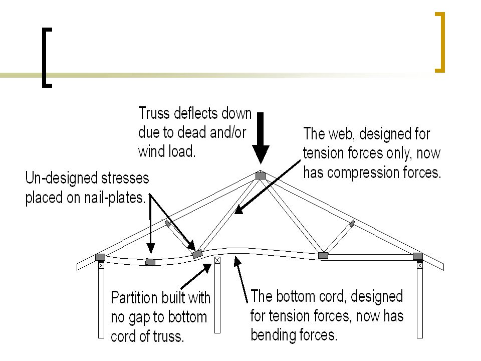
Trussed roofs Although we are not considering truss roofs in this subject- it is important that you, as potential builders realize the following- Trusses are designed to clear span between external walls. If trusses are supported anywhere mid-span, without being designed accordingly, stresses may be placed on individual truss components that they are not designed to take. The 10mm gap is to allow the trusses to deflect particularly when / if they are subjected to their full design load.

20
Lintels Section 6.3.6 Note adequate bearing required

21
Sill trimmers Section

22
Verandahs Beams, 6.3.7 Posts, 6.3.8

Similar presentations


 Compression element, Axial or bending2.6.1(p8) Compression element, Axial or bending Axial.>")


>")

