Download presentation
Presentation is loading. Please wait.

1
RHEEM COMMERCIAL WATER HEATING TRAINING

2
TRAINING COURSE OBJECTIVES
Introduction to Rheem Commercial Booklet Range appreciation Familiarise key design / installation criteria Introduction to manifolding Introduction to sizing Value added service

3
Commercial Water Heating course contents
Chapter 1 - Range overview - Commercial Booklet Chapter 2 - Heat Pump Chapter 3 - Commercial Solar Chapter 4 - Equaflow Manifolding Chapter 5 - Commercial Continuous Flow Chapter 6 - Commercial Storage Gas systems Chapter 7 - Raypak Heating and Hot Water Chapter 8 - Commercial Electric Chapter 9 - Guardian Warm Water Chapter 10 – Pump Sets Chapter Sizing and Selecting Chapter Commercial installation and design

4
Range Overview & Rheem Commercial Booklet
Chapter 1 Range Overview & Rheem Commercial Booklet

5
Chapter 2 - Commercial Heat Pump

6
COMMERCIAL HEAT PUMP LAYOUTS

7
COMMERCIAL HEAT PUMP LAYOUTS

8
Chapter 3 - Commercial Solar

9
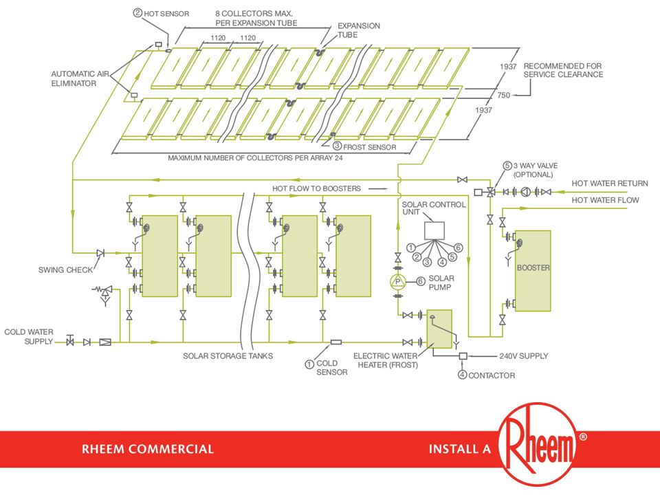
Commercial Solar Terminology Split / Pumped / Loline
Close Coupled / Thermosiphon / Hiline Direct / Indirect (Premier Hiline)
")
10
Commercial Solar Loline

11
Commercial Solar Loline
Pumped system Collectors and tank are split Fluid is pumped between collectors and tanks Can be on same level or different levels Direct system Consumed water passes through the collectors Partial frost protection In series boost

13
Commercial Solar Loline
325L and 410L vitreous enamel storage tanks Manifold tanks as required NPT200 collector Painted aluminium selective surface 7 riser tubes Good performance in all regions

14
Commercial Solar Loline
Frost Limited frost protection Frost sensor strategy Electric or gas frost heater Secondary Solar Recirculation Maximum solar energy use reduces energy use BMS output Run and fail status

15
Commercial Solar Premier Hiline

16
Commercial Solar Premier Hiline
Thermosiphon system Collectors and tank are close coupled Fluid rises through collectors naturally to tank Tank is always above collectors Indirect system Transfer fluid passes through the collectors and transfers heat to tank via heat exchanger Full frost protection In series or in- tank electric boost

17
Commercial Solar Premier Hiline
300L stainless steel tank Manifold systems as required 8 systems per array, multiple arrays possible S200 collector Steel collector Painted selective surface Good performance in all regions

19
Flat Plate vs Evacuated Tube Collectors

20
EQUA-FLOW MANIFOLDING
Chapter 4 EQUA-FLOW MANIFOLDING

21
EQUA-FLOW BASICS Equa-Flow Basics
The purpose of Equa-flow manifolding is to ensure water is used or generated equally in all cylinders in the manifold. Water will always take the path of least resistance, therefore ensuring equal resistance in the equaflow manifold is the key to equa-flow manifolding. First Principle Direction of flow must always be in the same direction through the manifold headers. This is sometimes referred to as “first in, last out”, but this can be confusing and needs to be understood. Other terminology could also be “water must exit the manifold at the opposite end to which it enters”.

22
EQUA-FLOW BASICS In Line Header diameters for cold/hot to be equal
Branch diameters for cold/hot to be equal Hydraulic water flow “In one side, out the opposite” Balanced performance per unit. Full delivery capacity from system Flow direction Out In Line Flow direction In Header sizes need to be equal to the diameter of cold supply to the plant and branch sizes should be at least one pipe size diameter smaller; Bushing down at the inlet/outlet connections is permissable.

23
EQUA-FLOW BASICS Flow direction Out Back to Back Flow direction In

24
EQUA-FLOW BASICS 1 B 0+1+1=2 A
A B 0+1+1=2 Water enters the first cylinder at point A, and thus travels zero distance through the manifold. Water exits the first cylinder and travels along the hot water manifold for a distance of 2 metres to point B, the end of the manifold. Total distance, or lineal resistance, equals 2 metres.

25
PATH of LEAST RESISTANCE
1 A B

26
MORE EQUA-FLOW PRINCIPLES
2 1 B 1 2 =6 =6 =6 It follows, then, that the hot and cold water branches do not necessarily need to be identical. All hot water branches must be identical, and all cold water branches must be identical, but the hot and cold branches can be different to each other. In this true life example, the plant room door was in the middle of the room and the heaters had to be placed on both sides of the door. The cold water and hot water manifolds were run at high level, above the door, and long droppers were run for each cold water branch. In this example, the cold branches could be 2m long, and the hot branches are 1m long, as well as the distance between tanks is different. From Point A to Point B, including the branches: The first heater has a resistance of = 6m. The second heater has a resistance of = 6m And the third heater has a resistance of = 6m

27
ANGLED MANIFOLD 1 3 + bend A B The same is true for angled manifolds.
The third heater is encumbered by a manifold length 2 metres longer than the manifold between heaters one and two, plus one bend. This applies to both the cold and hot water manifolds. Following the manifold principles, each cylinders’ resistance is as follows: Cylinder 1: Cold manifold = zero Hot manifold = bend Total = bend Cylinder 2: Cold manifold = 1 Hot manifold = bend. Cylinder 3: Cold manifold = bend Hot manifold = zero The key principle is that direction of flow is maintained in the same direction

28
BACK TO BACK MANIFOLD 0.75 1 1 A B 1 1 0.75
H2: = 2.75 H4: = 2.75 H6: = 2.75 A H5: = 2.75 B H1: = 2.75 H3: = 2.75 Back to Back manifolds can be a little hard to follow, but the principles remain unchanged. In the illustrated example, the distance between branches between heater 1 &2 and 5 &6 is shorter than the distance between other branches. The distance travelled in each header is identical for hot and cold. Once again, the key principle is that direction of flow is maintained in the same direction. 1 1 0.75

29
EQUAFLOW PRINCIPLES IN PRACTICE

30
COMPLICATED EQUAFLOW PRINCIPLES IN PRACTICE
When designing/ inspecting complicated manifolds consideration must be given to primary loops as well as hot and cold headers

31
EQUAFLOW PRINCIPLES IN PRACTICE

32
COMPLICATED EQUAFLOW PRINCIPLES IN PRACTICE

33
TO WATER HEATER MANIFOLD
BRANCHES NEVER use non-return valves or pressure limiting valves in the branch These create imbalance in the branches Non-return and pressure reducing valves must be in a train on the cold water inlet COLD WATER SUPPLY TO WATER HEATER MANIFOLD Never use non-return valves or pressure limiting valves in branches. These create pressure imbalances between the branches and will affect equaflow performance. All control valves must be installed in a train on the cold water inlet.

34
BRANCHES Only an isolating valve and union must be in the branch
Full flow gate or ball valves must ONLY be used NEVER use duo valves or loose jumper valves These create imbalance in the branches So far we have been concentrating on flow direction and balancing resistance in the headers. Branch resistance is equally important. Each branch must ONLY contain an isolating valve and union Use ONLY gate valves or ball valves, both fully open. Duo valves and loose jumper valves create imbalance in the branches. Further, both of these valves act as non return valves and can affect water flow in certain applications. This will be discussed in more detail further in the session.

35
BRANCHES T PIECE Last branch should be a T piece, not an elbow, to maintain equal resistance in all branches Ideally, the last branch in a manifold should be a T piece, not an elbow, in order to maintain equal resistance in all branches.

36
Chapter 5 - Commercial CFWH

37
RHEEM INDOOR CFWH – FLUE SYSTEMS
USE MM AND FF ADAPTERS IF HORIZONTAL LENGTH OF HORIZONTAL TERMINATING FLUE EXCEEDS 2.7M TRIM RING USE CONDENSATE DRAIN & TRAP IF VERTICAL SECTION OF HORIZONTAL TERMINATING FLUE EXCEEDS 2M

38
Rheem Multipak, Tankpak, Commpak and Commpak Plus Commercial Continuous Flow
Hot Water Solutions

40
Chapter 6 - Commercial Gas Storage

41
RHEEM Commercial Gas Storage
Work horse of the industry 3 input sizes – 50, 110, 200MJ/hr Indoor and outdoor models Multi-fin flue technology Flue damper Hot Surface Ignition Up to 82oC Room sealed flue

42
HD Gas Layout

43
631275 Room Sealed Flue Converts outdoor model to indoor room sealed
Ideal where no ventilation, contaminated air supply or fluing to roof impractical 3m and 3 x 90o bends Re-use flue terminal Kit P/No

45
Chapter 7 – Raypak Heating and Hot Water

46
Raypak Layouts

47
Chapter 8 - Commercial Electric Storage

48
RHEEM Commercial Electric Storage
Work horse of the industry 2 x 3 element models – 50 & 315L 1 x 6 element model – 315L Up to 36kW output Indoor and outdoor installation Heavy Duty enamel Larger anode Models up to 82oC

49
HD Electric Layout

50
Chapter 9 - Rheem Guardian Warm Water

51
Chapter 10 - Pump Sets

52
Deluxe Pump Sets Deluxe Models UPS 20-60N and 32-80N pumps
Individual Auto, Off, Manual switches Individual Run and Fail indicators Timer control Isolation and check valves included BMS output

53
Standard Pump Sets Standard Models UPS 20-60N and 32-80N pumps
Single Auto, Off, Manual switch Timer control Isolation and check valves included

54
Chapter 11 Sizing and selecting...

55
Energy Consumption It takes 4.2kJ of heat energy to raise 1litre of water (or 1 kg) of water 1 degree E = L x 4.2 x dT Example : To raise 500 litres by 32 degrees (from 10C to 42C) Energy consumption = 500 x 4.2 x 32 = 67,200kJ or 67.2MJ Plant efficiency must also be considered. If the plant operates at 80% efficiency, then; Energy required = 67.2 / 0.8 = 84MJ O/H 14 - Why You Should Recommend Rheem TAB - Rheem leads the way with Hot Surface Ignition, the safest, simplest and smartest way to control water heaters. TAB - We offer a full 5 year replacement warranty for commercial applications, 10 year for domestic. TAB - With features, such as HSI, high thermal efficiency, polyurethane insulation and flue damper, we lead the way in energy conservation and reduced running costs. TAB - Rheem incorporates the latest technology features into all of its designs. TAB - At the end of the day, however, lots of hot water when you need it, is still the main criteria. Only Rheem mains pressure water heaters provide true multipoint operation. TAB - And backing our first class products is a nationwide network of service to ensure your customers are never left out in the cold and the right technical advice from a professional and friendly sales team.
 of water 1 degree E = L x 4.2 x dT Example : To raise 500 litres by 32 degrees (from 10C to 42C) Energy consumption = 500 x 4.2 x 32 = 67,200kJ or 67.2MJ Plant efficiency must also be considered. If the plant operates at 80% efficiency, then; Energy required = 67.2 / 0.8 = 84MJ O/H 14 - Why You Should Recommend Rheem. TAB - Rheem leads the way with Hot Surface Ignition, the safest, simplest and smartest way to control water heaters. TAB - We offer a full 5 year replacement warranty for commercial applications, 10 year for domestic. TAB - With features, such as HSI, high thermal efficiency, polyurethane insulation and flue damper, we lead the way in energy conservation and reduced running costs. TAB - Rheem incorporates the latest technology features into all of its designs. TAB - At the end of the day, however, lots of hot water when you need it, is still the main criteria. Only Rheem mains pressure water heaters provide true multipoint operation. TAB - And backing our first class products is a nationwide network of service to ensure your customers are never left out in the cold and the right technical advice from a professional and friendly sales team.")
56
Typical Hot Water Usage Assumptions
Offices Office peak period 60 minutes Water per person litres Area per person 10m2 Occupants Gymnasium peak period 30 minutes Water per person litres

57
Typical Hot Water Usage Assumptions
Food Service Restaurant Peak Period – 2 hours (temperature requirements) Bistro per Meal 5.0 litres Coffee Shop per Meal 3.5 litres Auditorium per Meal 3.0 litres Restaurant per Meal 5.5 litres Takeaway Shop per Meal Café per Meal litres Hotel Kitchen per Meal 6.0 litres Remember to consider commercial temperature requirements
 Bistro per Meal 5.0 litres. Coffee Shop per Meal 3.5 litres. Auditorium per Meal 3.0 litres. Restaurant per Meal 5.5 litres. Takeaway Shop per Meal. Café per Meal 3.0 litres. Hotel Kitchen per Meal 6.0 litres. Remember to consider commercial temperature requirements.")
58
Typical Hot Water Usage Assumptions
Apartments Peak period 60 minutes Bed-sitter litres 1 Bedroom litres 2 Bedroom litres 2 Bedroom w/en suite litres 3 Bedroom litres 3 Bedroom w/en suite litres 4 Bedroom litres Penthouse litres

60
Typical Hot Water Usage Assumptions
Motel Motel peak period 60 minutes (Assume 2 people per room) Shower 1 & 2 Star 20 litres /person Shower 3 Star 25 litres /person Shower 4 Star 30 litres /person Shower 5 Star 45 litres /person Shower Family/Spa 100 litres /person
 Shower 1 & 2 Star 20 litres /person. Shower 3 Star 25 litres /person. Shower 4 Star 30 litres /person. Shower 5 Star 45 litres /person. Shower Family/Spa 100 litres /person.")
61
Sizing example... Motel 100 rooms 5 star accommodation
Central electric plant Moderate climate Refer to commercial booklet...

62
Sizing example... Motel Showers = 50 x 2x 45 = 4,500L/1hr peak
Moderate climate = 50oC rise Central electric plant: 5 x with 6 x 6kW elements

63
Hot Water Usage Assumptions
Nursing Home Peak period 180 minutes Bedpan 2.5 litres / bed Shower 25 litres / bed Cleaning water 10 litres / bed Water per meal 5.5 litres Laundry peak 300 minutes Laundry (1.2kg per bed) 10 litres / kg
 10 litres / kg.")
64
Selecting a water heating system
Usage profiles...Have they changed? Peak Period in Litres/hr (e.g. 1hr) Redundancy Daily Load in Litres (Solar)... Water delivery Temperatures Plant Location - Indoor or Outdoor Flue location & termination (room sealed?) Circulation Systems...considerations
 Redundancy. Daily Load in Litres (Solar)... Water delivery Temperatures. Plant Location - Indoor or Outdoor. Flue location & termination (room sealed ) Circulation Systems...considerations.")
65
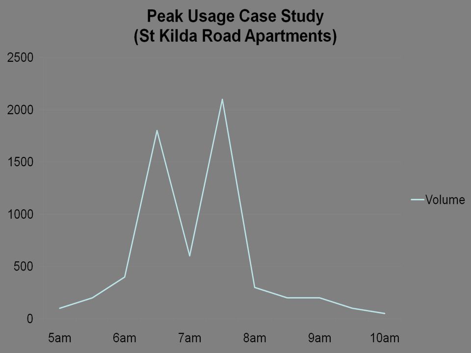
Sporting Facility Case Study Football Club - Tasmania

66
Sizing example... Local football club
15 shower 6 litres per minute (hot) 35 players inc umpires Commercial heat pump system Refer booklet...
 35 players inc umpires. Commercial heat pump system. Refer booklet...")
67
Sizing example... Players and Umpires = 35 Shower time, say 10 mins
Peak duration = 30mins Showers = 35 x 6L/min x 10 = 2,100 litres Plant selection: 6 x storage tanks 1 x heat pump ambient =244L/hr = 9hrs

68
SELECTION & SIZING... Diversity...
The difference between the maximum possible load on a water heating system if all outlets were in use at once and the “likely” load at any given time. Example... In a multi story accommodation building, only a predictable percentage of taps will be turned on at any given time, however it can be expected that all taps in a shower block of a sporting facility can be turned on at once and will require full heated water flow.

69
CFWH PLANT or STORAGE PLANT... What to consider?
SELECTION & SIZING CFWH PLANT or STORAGE PLANT... What to consider? Footprint availability e.g. solar Storage volume? Maintenance/removal Flow rates Gas and water pressure Fluing Energy/fuel types

70
Commercial Installation and Design Requirements
Chapter 12 Commercial Installation and Design Requirements

71
82oC Dead Leg Operation

72
Primary Pump Requirements
Used for Raypak, Solar and Heat Pump Non return valve is not required after primary pump. Spindle must be horizontal Pump is not weather proof – must be covered Isolation Valve Primary Pump Note: Pump shaft must be horizontal

73
NOT EQUA-FLOW PUMP SPINDLE VERTICAL
There were two main problems with the installation. The pumps were installed with the spindle in the vertical orientation. This is a problem as these circulators are water cooled and rely on water to flow around the armature to keep the motor cool. Installed as shown, an air pocket can exist which may lead to little or no flow and ultimately to pump failure. This is often a hard message to get across, typically asking that the pump be installed with the shaft in the horizontal orientation. Most plumbers believe the pumps in this photo are installed horizontally. And whilst it is true the water flow is horizontal, the axis of the shaft is vertical. As it turned out, the pump shaft was broken on one of the heat pumps which explains why the unit tripped out immediately - With no water flow, the heat pump cannot transfer the heat it generates, leading to high discharge pressure in the refrigerant. 2) Of more importance however is that the primary flow and return between the two banks was, in fact, not plumbed in equa-flow. The direction flow to the two branch headers is from bottom to top, or from closest tank to furthest tank. The section of main header between the two branch headers is less than 300mm, yet, not plumbed in equaflow, is sufficient for water flow to favour one bank over the other. In this case, the closest bank.
 Of more importance however is that the primary flow and return between the two banks was, in fact, not plumbed in equa-flow. The direction flow to the two branch headers is from bottom to top, or from closest tank to furthest tank. The section of main header between the two branch headers is less than 300mm, yet, not plumbed in equaflow, is sufficient for water flow to favour one bank over the other. In this case, the closest bank.")
74
Clearances

75
CASE STUDY #2 Rheem Commercial Water Heating Systems
Rheem Solar preheated, gas storage with a warm water system.

76
Commercial application – Large nursing home

77
Including a commercial laundry

78
Commercial kitchen

79
Commercial sinks

80
Electric boost on sink

81
Commercial dishwashing machine

82
Water must be at sanitizing temperature i.e. 77 degrees

83
The solar array To achieve the energy rating for the building, solar has been chosen. Often solar is a preferred method to achieve the energy reduction on site. Note - north facing collectors Note - the fall protection The panels are set in two arrays of 8 collectors

84
16 Rheem solar panels – ‘primary source of heat’ Each square meter(approx) of panel requires approx. 60 litres of solar storage tank capacity!

85
Collector connections

86
Primary flow and return to solar panels.

87
Temperature probe wired to solar controller and to the circulating pump. It works on a 8 degree C differential.

88
Automatic air eliminator on the return line out of the panels.

89
The return hot water line to storage tanks
Note the pipe insulation to reduce heat loss which is measured in ‘ watts ‘ per meter Lagging must be UV resistant and meet AS3500.4

90
Four Rheem 430 litre solar storage cylinders ( 1720 litre capacity )
")
91
Rheem Gas boost mains pressure storage units.

92
Rheem Solar controller
Green light indication of system cycle. Note - the solar return pipe work from the panels.

93
Primary flow and return from solar panels
Note – the isolation valves Note – the pipe lagging

94
Commercial site assistance

95
THANK YOU FOR YOUR TIME TODAY
We trust you have enjoyed and benefited from this training course...

Similar presentations

: Safety Systems Overview>")


>")


