Download presentation
Presentation is loading. Please wait.

1
Digital Logic Design Lecture 22

2
Announcements Homework 7 due today Homework 8 on course webpage, due 11/20. Recitation quiz on Monday on material from Lectures 21,22

3
Agenda Last time: – Programmable Logic Devices (5.7-5.10) This time: – New topic: Flip-flops The Basic Bistable Element (6.1) Latches (6.2) Timing Considerations (6.3) Master-Slave Flip-Flops (6.4) Edge-Triggered Flip-Flops (6.5)
 This time: – New topic: Flip-flops The Basic Bistable Element (6.1) Latches (6.2) Timing Considerations (6.3) Master-Slave Flip-Flops (6.4) Edge-Triggered Flip-Flops (6.5)")
4
Sequential Networks The logic networks studied so far are combinational networks: – The outputs at any instant depend only upon the inputs present at that instant. Sequential Network: – The outputs at any instant are dependent not only upon the inputs present at that instant but also upon the past history of inputs. Sequential networks have memory. – The information preserved is referred to as the internal state, secondary state, or state of the network.

5
Sequential Networks Synchronous sequential network – Behavior is determined by the values of the signals at only discrete instants of time. – Master-clock generator which produces a sequence of clock pulses that sample the input. Asynchronous sequential network – Behavior of the network is immediately affected by the input signal changes.

6
Flip-Flop The basic logic element that provides memory in many sequential networks. Flip-flop itself is a simple sequential network. – All sequential networks require the existence of feedback. – Feedback is present in flip-flop circuits. Flip-flop has two stable conditions. – Each of this is associated with a state or storage of a binary symbol.

7
The Basic Bistable Element

9
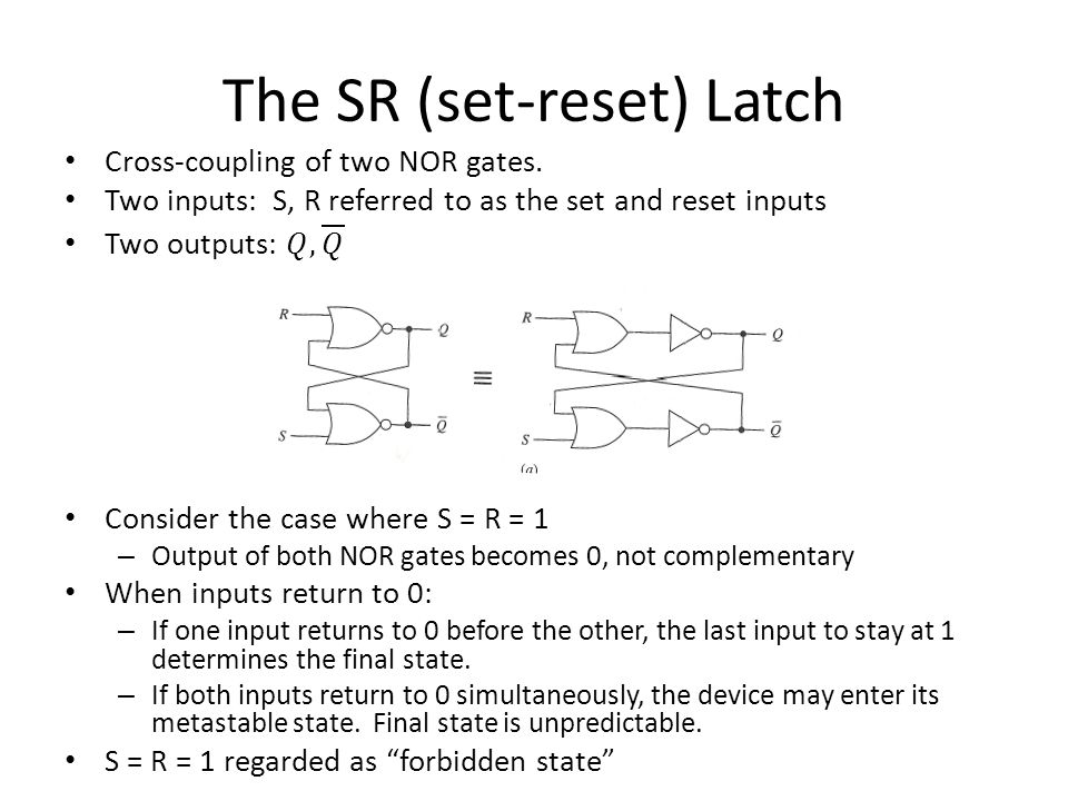
Has no inputs. When power is applied, it becomes stable in one of its two stable states and remains in this state until power is removed. To be useful, must be able to force the device into a particular state. A flip-flop is a bistable device, with inputs, that remains in a given state as long as power is applied and until input signals are applied to cause its output to change. Inputs to flip-flops: – Asynchronous or direct input: a signal change produces an immediate change in the state of the flip-flop. – Synchronous input: A signal change does not immediately affect the state of the flip-flop. Affects it only when some control signal (clock) occurs.
 occurs..")
10
Latches Latches are one class of flip-flops The timing of the output changes is not controlled – The output responds immediately to changes on the input lines. – Input lines are continuously being interrogated. Sections 6.4,6.5: flip-flops in which the timing of the output changes is controlled.

11
The SR (set-reset) Latch
 Latch")
13
The SR Latch Next state is the same as the previous state.

15
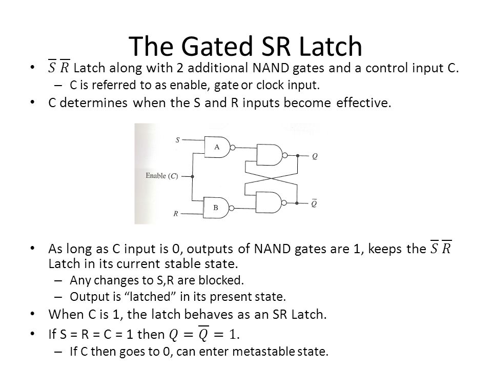
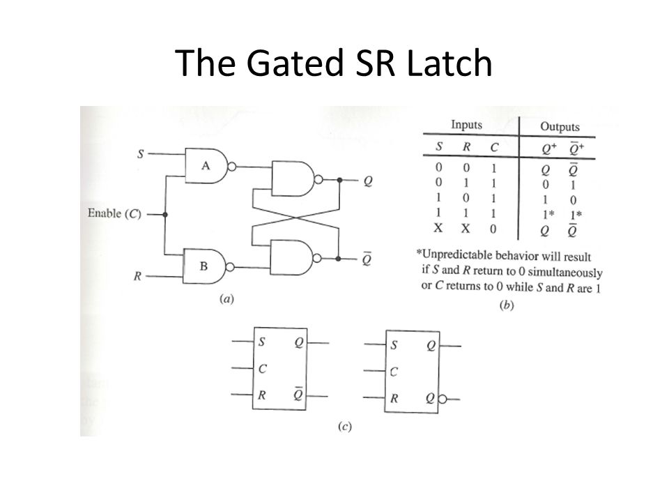
The Gated SR Latch

18
The Gated D Latch The latches discussed thus far each has an input combination that is not recommended. The gated D (data) latch does not have this problem. Gated SR-latch in which a not-gate is connected between the S and R terminals. Why does this help?
 latch does not have this problem. Gated SR-latch in which a not-gate is connected between the S and R terminals. Why does this help .")
19
The Gated D Latch

20
Timing Considerations Responses to inputs are not really immediate, but occur after some appropriate time delay. To achieve desired responses, certain timing constraints must be satisfied.

21
Propagation Delays In general, these may be different.

22
Timing Diagram

23
Minimum Pulse Width

24
Setup and Hold Times

25
Unpredictable Response in a gated D latch

Similar presentations


 3 classes of.>")

 Shift Registers and Application Counters (Types,>")

 The slides included herein were taken from the materials accompanying Fundamentals.>")


 S – R Latch “Cross-Coupling” two NAND gates gives the S -R Latch:>")


