Download presentation
Presentation is loading. Please wait.

1
ENS 207 engineering graphics
Lecture 2: sketching

2
Freehand Sketching Freehand sketches are a helpful way to organize your thoughts and record ideas. They provide a quick, low-cost way to explore various solutions to design problems so that the best choices can be made.

3
TECHNIQUE OF LINES line patterns
The chief difference between a drawing and a freehand sketch lies in the character or technique of the lines. A good freehand line is not expected to be as rigidly straight or exactly uniform. A good freehand line shows freedom and variety, whereas a line drawn using CAD or instruments should be exact. line patterns

4
Lineweights Even in freehand drawings, thick lines should be twice the width of thin lines. Thicknesses do not have to be exact, but there should be an obvious difference between thick and thin lines. Because visible lines and cutting-plane lines are the two thick line patterns, other lines should be distinctly thinner in comparison. To draw thick and thin lines freehand, you might like to keep two pencils handy, one that is razor sharp for thin lines and another that is dulled, to create thicker lines. As the sharp point becomes dulled, switch it with the dull pencil, and sharpen the other, so that there is always one sharp and one dulled point ready to use.

5
FREEHAND LINES The main difference between an instrument or CAD drawing and a freehand sketch is in the appearance of the lines. A good freehand line is not expected to be precisely straight or exactly uniform, as is a CAD or instrument-drawn line. Freehand lines show freedom and variety. Freehand construction lines are very light, rough lines. All other lines should be dark and clean.

6
Edges and Vertices Edges Vertices Points
An edge of the solid is formed where two surfaces intersect. Edges are represented in drawings by visible or hidden lines. Vertices A vertex (plural, vertices) of a solid is formed where three or more surfaces intersect.. Points A point is used to represent a location in space but has no width, height, or depth.
 of a solid is formed where three or more surfaces intersect.. Points. A point is used to represent a location in space but has no width, height, or depth.")
7
For Example: 1. Visible 2. Hidden 3. Center
From Bertoline: Figure 2.38 / Pg 42 In engineering and technical drawing, it is important that hidden features be represented, so that the reader of the drawing can clearly understand the object. Thus we need hidden lines to emphasize that those features exist and are hidden in that particular view. We also need center lines to understand how the features defined in the 2D views translate into 3D. NOTE: It must be emphasized that hidden lines and center lines are used only on Orthographic projection drawings, never on isometric drawings Q: Do we need a convention for what line to show if two lines fall on top of each other? A: Yes! Otherwise features which are more important (eg: visible lines) would be overridden by less important features (eg: hidden lines) and the resulting drawing would be interpreted inaccurately. The next slide shows the convention followed. 2. Hidden 3. Center
 would be overridden by less important features (eg: hidden lines) and the resulting drawing would be interpreted inaccurately. The next slide shows the convention followed. 2. Hidden. 3. Center.")
8
Horizontal line Vertical line

9
Small Circle Method 1 : Starting with a square
1. Lightly sketching the square and marking the mid-points. 2. Draw light diagonals and mark the estimated radius. 3. Draw the circle through the eight points. Step 1 Step 2 Step 3

10
Arc Method 1 : Starting with a square
Method 2 : Starting with a center line

11
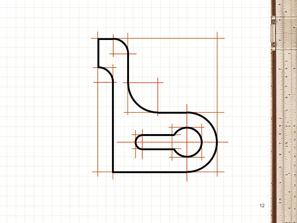
Example

13
PROPORTIONS Sketches should be proportional. A square should look like a square, and a rectangle like a rectangle. Graph paper is very helpful in sketching proportionally, but it is still sometimes difficult to be accurate even with graph paper.

14
CURVES Curved shapes are best sketched by first defining points along the curve, then lightly sketching the curve between the points.

15
Circles and Ellipse An ellipse can be sketched by first sketching a perpendicular axis, then locating four marks on the centerlines that are approximately equal to major and minor axis distances. Sketch a light curve, make any corrections necessary, and darken in the elliptical shape.

16
Introduction to Isometric Projection
CUBE Isometric Projection: One type of axonometric pictorial (3-D) projection ‘Iso-’ means ‘equal ‘metric projection’ means ‘a projection to a scaled measure’ The three dimensions are not only shown in one view, but also the dimensions can be scaled from this drawing START WITH A CUBE All of the normal drawing planes (top, front, side) are equally foreshortened or tilted, and all of the major axes (X, Y, Z) are at equal rotations from each other (120 degrees apart), as in the illustration above. And, because all of the major planes are equally foreshortened, all of the measurements in these planes are equal as well as shown above. This means that the same measuring scale may be used in drawing both the width, height, and depth of objects. Isometric means equal measure All planes are equally or proportionately shortened and tilted All the major axes (X, Y, Z) are 120 degrees apart AU 2005
 projection. ‘Iso-’ means ‘equal. ‘metric projection’ means ‘a projection to a scaled measure’ The three dimensions are not only shown in one view, but also the dimensions can be scaled from this drawing. START WITH A CUBE. All of the normal drawing planes (top, front, side) are equally foreshortened or tilted, and all of the major axes (X, Y, Z) are at equal rotations from each other (120 degrees apart), as in the illustration above. And, because all of the major planes are equally foreshortened, all of the measurements in these planes are equal as well as shown above. This means that the same measuring scale may be used in drawing both the width, height, and depth of objects. Isometric means equal measure. All planes are equally or proportionately shortened and. tilted. All the major axes (X, Y, Z) are 120 degrees apart. AU")
17
Making an Isometric Sketch
Defining Axis 30o 60o Isometric Axis Derive the axes from a vertex of the cube AU 2005

18
Three planes The three planes of an isometric axis are defined as the
left, right, and top planes, respectively

19
Making an Isometric Sketch
Axis Convention Height Choose the longest dimension to be the width (or the depth) for optical stability Width Depth The above slide is used to indicate the manner in which the width, depth and height of a 3-dimensional object is seen in an Isometric Sketch. Note the assignments of height, width, and depth to the axis. The front view direction is shown. Please emphasize this convention to the students. Front view Isometric Axis Convention AU 2005
 for optical stability. Width. Depth. The above slide is used to indicate the manner in which the width, depth and height of a 3-dimensional object is seen in an Isometric Sketch. Note the assignments of height, width, and depth to the axis. The front view direction is shown. Please emphasize this convention to the students. Front view. Isometric Axis Convention. AU")
20
Object for Practice How to derive this object from a rectangular piece of wood? Shape it in to a rectangle with maximum dimensions (so as to fit the required object) on the three axes Chisel out the unwanted parts…. Slides follow. NOTE: No scale provided due to lack of measurements of blocks. TA’s – Get the blocks from the Instructors Console and distribute them to all the tables. AU 2005
 on the three axes. Chisel out the unwanted parts…. Slides follow. NOTE: No scale provided due to lack of measurements of blocks. TA’s – Get the blocks from the Instructors Console and distribute them to all the tables. AU")
21
Blocking in the Object Begin with Front Face
Height Width Identify the size of the front view of the object and sketch its outside dimensions on the Isometric view. AU 2005

22
Blocking in the Object: Add Side Face
Height Depth Side Face Once the front view outside dimensions are added on the isometric sketch, add the side view dimensions. AU 2005

23
Blocking in the Object: Add Top Face
After front and side views are sketched on the isometric drawing, then add the top view. AU 2005

24
Adding Detail Cut Outs – Part 1
The order of adding the details is important. They build upon each other. AU 2005

25
Adding Detail Cut Outs – Part 2
Note that lines parallel to axes AU 2005

26
Adding Detail Cut Outs – Part 3
Note that lines parallel to axes are drawn first, then oblique lines are determined from their intersections. AU 2005

27
Darken Final Lines - Part 4
Note: All visible edges will be darkened Construction lines can be left in but must be much lighter than the final lines. AU 2005

28
PLANNING YOUR DRAWING OR SKETCH
When laying out a drawing sheet, you will need to consider: • the size and scale of the object you will show • the sheet size • the measurement system (units) for the drawing • the space necessary for standard notes and title block.
 for the. drawing. • the space necessary for standard notes. and title block.")
Similar presentations