Download presentation
Presentation is loading. Please wait.

1
Practical Application of Finite Element Analysis to the Design of Post-Tensioned and Reinforced Concrete Floors Jonathan Hirsch, P.E.

2
Computer Assisted Design of Concrete Floors Types of programs available Advantages of each Why specialized finite element software is necessary for PT design

3
Computer Assisted Design of Concrete Floors The design process using 3-D finite element analysis Project examples

4
Types of Programs Available 2-D strip method 3-D finite element method Linear elastic Non-linear

5
2-D Strip Method Structure analyzed with one model per beam, one-way slab, or two-way slab bay Equivalent frame method used for two- way slabs Easy to understand behavior Good for highly repetitive structures

6
Flat Plate Example

7
Transverse direction

8
Longitudinal direction

9
3-D finite element method Visual modeling / input Accuracy continuity effects (elastic reactions) load path complicated loads (including lateral) restraint effects torsion
 load path complicated loads (including lateral) restraint effects torsion")
10
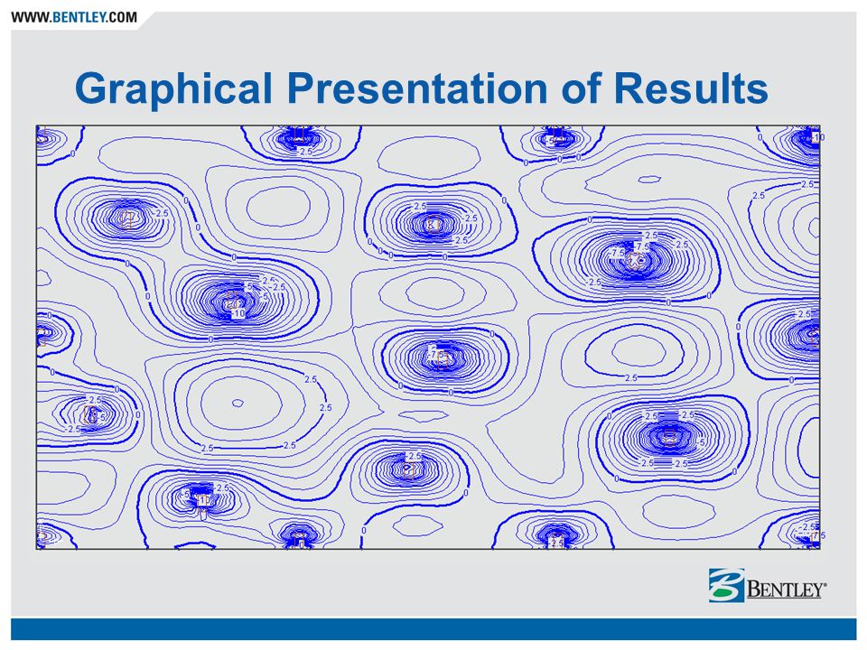
3-D finite element method Graphical presentation of results Less cumbersome – work with one model instead of numerous Easier to incorporate changes Loadings Concrete geometry Construction Issues »Low Concrete Strength »Broken Strands

11
Las Olas River Condominiums 43 Story Fort Lauderdale, FL Suncoast Post- Tension

12
Visual modeling / input Speed CAD like interface Reduce chances for input error Automatic mesh generation

13
River City Apartments, Brisbane 1650 mm Transfer Slab

14
River City Apartments – Tendons Robert Bird and Partners

15
Accuracy of 3-D FE Analysis Continuity Effects Load Path Complicated Loads Generally leads to more optimal design

16
Accuracy of 3-D FE Analysis Restraining Effects Torsion

17
Continuity Effects

19
Beam and Slab: Relatively straightforward load path

20
Beam and Slab: More difficult load path

21
Prestress tendon profile variations

22
Bending moments …

23
Loads ….. Self weight is automatically calculated Superimposed loadings easily input

24
Straightforward line load

25
Complicated point and line loads

26
Restraining Effects Normally ignored by 2-D programs Can be calculated and accounted for by 3-D finite element programs Important for serviceability of structure Important for strength of structure (hyperstatic effects)
")
27
Torsion Normally ignored by 2-D programs (potentially creating a conservative design) Can exist in 3-D finite element model and therefore should be designed for
 Can exist in 3-D finite element model and therefore should be designed for")
28
Torsion

30
Graphical Presentation of Results

32
Finite Element Basics Using shell elements to model concrete floors In plane forces Out of plane forces Related in irregular slabs (change of centroid)
")
33
In Plane Forces

34
Out of Plane Forces

35
Plate Considerations Resolution of Txy Integrated forces in equilibrium with nodal loads

36
Interaction of In Plane/Out of Plane Fx’ = Fx Vxy’ = Vxy Vxz’ = Vxz My’ = My - Fx d Mxy’ = Mxy - Vxy d

37
Using Shell Elements to Model Beams Deep beam behavior Torsion stiffness of beams using shell elements Transfer of moment through large step

38
Deep Beam Behavior

40
Torsion Stresses

41
Moment Transfer Through Step Beam

42
Orthotropic Element Properties

43
Hyperstatic (Secondary) effects …..
 effects …..")
44
Hyperstatic effects …

45
Hyperstatic effects …..

46
“Complete Secondary (Hyperstatic) Effects” Allan Bommer PTI Journal - January 2004
 Effects Allan Bommer PTI Journal - January 2004")
47
Post-Tensioning Loadings Balance Loading Hyperstatic Loading

48
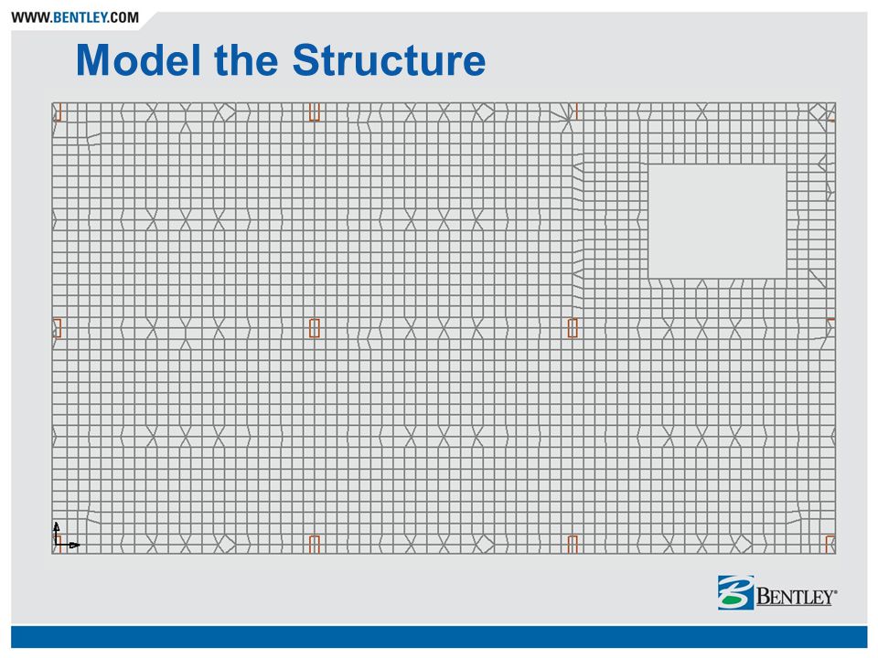
The 3-D Finite Element Design Process Model the structure Apply the loads Lay out the tendons (if PT) Draw design strips (define cross-sections) Perform the design Process results
 Draw design strips (define cross-sections) Perform the design Process results")
49
Model the Structure

52
Apply the Loads (Dead Loads)
")
53
Apply the Loads (Live Loads)
")
54
Lay Out Tendons (Banded)
")
55
Lay Out Tendons (Distributed)
")
56
Lay Out Tendons

57
Deflection With Initial Tendon Layout

58
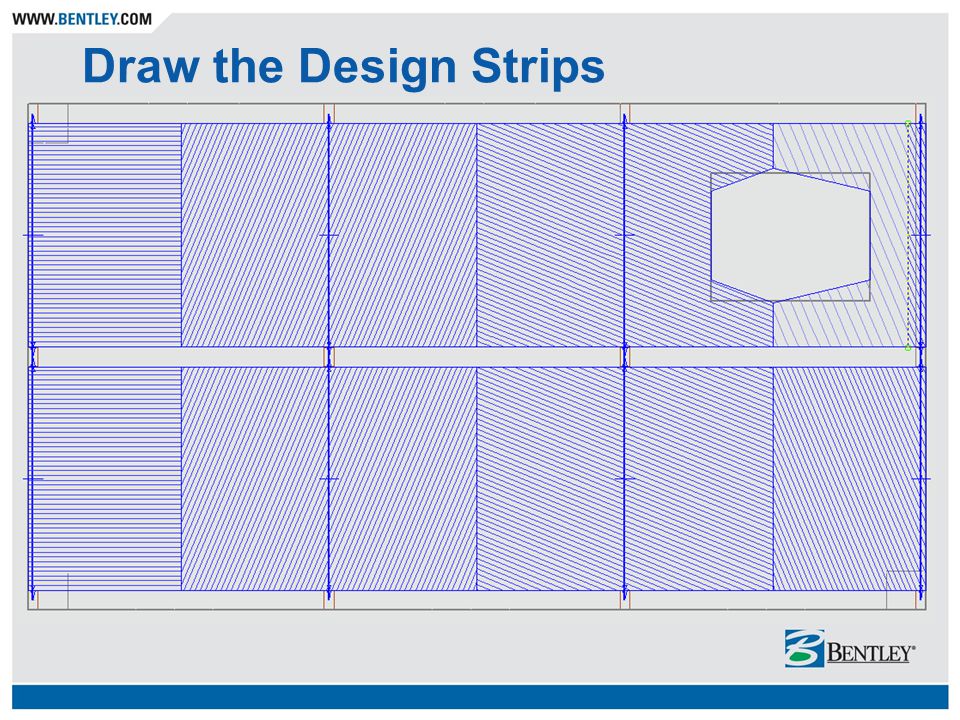
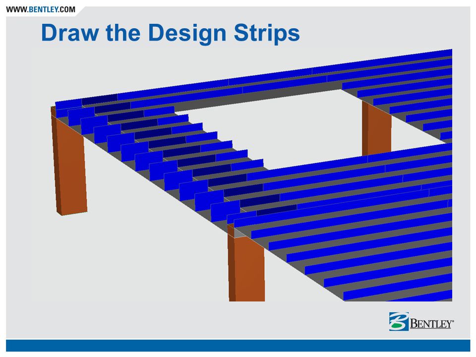
Draw the Design Strips

64
Perform the Design

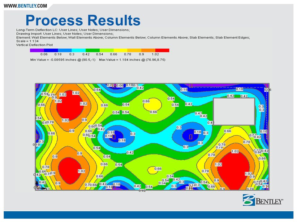
68
Process Results

83
Special Considerations Lateral Analysis / Design Punching Shear Analysis / Design Restraining Effects Pour Strips, etc. Mat Foundations

84
Punching Shear

86
SR=1.25 Punching Shear …….. stress ratio exceeds unity

87
Punching Shear …….. without penetrations, stress ratio < 1

88
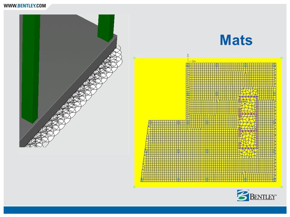
Mats

90
48” Mat: DL + LL + WL Bearing pressure Max = 2560 psf Min = 690 psf

91
24” Mat: DL + LL + WL Bearing pressure Max = 3450 psf Min = 0 psf (10 iterations)
")
92
24” Mat: DL + LL + WL Bearing pressure Max = 3450 psf Min = 0 psf (10 iterations)
")
93
Bridgewater Place, Leeds Mixed Use: Office / Residential Connell Mott McDonald Matthew Consultants

94
Minneapolis Institute of Arts …….Soffit view Top view………

95
Sheraton Keauhou Bay Resort Keauhou Kona, Hawaii

96
Structural Systems (UK) Ltd
 Ltd")
97
Westbridge Wharf Leicester Strongforce / Laing O’Rourke

98
3 residential buildings 9 levels each Westbridge Wharf

99
St. Lucia Luxury Condominiums Destin, Florida Suncoast Post-Tension

101
Royal Palm Plaza Boca Raton, FL Tendon Systems, Inc.

103
Opus Architects and Engineers

104
Jonathan Hirsch, P.E. Jonathan.Hirsch@bentley.com

Similar presentations


 Superstructure – Concrete Bridges>")


