Download presentation
Presentation is loading. Please wait.

1
Planning and Design of Airport Infrastructures
10th Transportation Infrastructure Lecture by Sri Atmaja P. Rosyidi, ST., M.Sc., Ph.D., P.Eng. Universitas Muhammadiyah Yogyakarta

2
What is PLANNING ? Planning Philosophy in Airport Design
The efficient airport as a whole is that which provides the required capacity for aircraft, passenger, cargo and vehicle movement with maximum passenger, operator and staff convenience and at lowest capital and costs.

3
Environmental Problems !!!
Using Planning Save Costs !!! Minimize Problems !!! Excellent Transportation System !! High Costs !!! Environmental Problems !!! Bad transport!!! Without Planning

4
The Planning System Planning airport is complicated by the diversity of facilities and services which are necessary for the movement of aircraft, passengers and cargo and the ground vehicles associated with them, and the necessity to integrate their planning. Airport planning is the evaluation of a compromise between conflicting features of the best plan for each of the individual facilities for providing the greatest degree of flexibility and expansibility for future development.

5
What’s NEEDED in the airport planning!
An Airport Master Plan : “presents the planners conception of the ultimate development of a specific airport”. Master plan are applied to the modernization and expansion of existing airports and to construction of new airports.

6
Airport Master Plan as A Guide
Development of physical facilities of an airport (aviation or non aviation use). Development of land uses for areas surrounding an airport. Determination of the environmental effects of airport construction and operation Establishment of access requirements of the airport.
. Development of land uses for areas surrounding an airport. Determination of the environmental effects of airport construction and operation. Establishment of access requirements of the airport.")
7
Type of Activity Involved in the Master Plan Process
Policy/co-ordinative planning. Economic Planning. Physical Planning. Environmental Planning. Financial Planning.

8
Steps in Planning Process
Prepare a master planning work programme. Inventory and document existing condition. Forecast future air traffic demand. Determine gross facilities requirements and preliminary time-phased development of same. Evaluating existing and potential constraints. Agree upon relative importance or priority of various elements such as airport type, constraints, political and other consideration. Develop several conceptual or master plan alternatives for purposes of comparative analysis. Review and screen alternative conceptual plans. Select most acceptable and appropriate alternative.

9
Plan Update Recommendations
Master plan should be … reviewed at least annually and adjusted as appropriate to reflect conditions at the time of review. thoroughly evaluated and modified every five year, or more often if change in economic, operational, environmental and financial condition indicate an earlier need for such revision.

10
Limitation of Master Plan
Master plan is just a guide and nothing more. Master plan is not implementation programme. Master plan does not develop specific with respect to improvements, it is only a guide to the types of improvements.

11
Preplanning Considerations
Pre-Definition Successful expansion (existing airport) and development (new airport) will result from the guidelines established in an airport master plan. Accordingly, if a master plan is to be useful to airport authorities certain preplanning requirements must be understood and followed.
 and development (new airport) will result from the guidelines established in an airport master plan. Accordingly, if a master plan is to be useful to airport authorities certain preplanning requirements must be understood and followed.")
12
Preplanning Considerations
Preplanning considerations for providing the frame works of an effective and implemented airport master plan, include the following : Pre-planning co-ordination. Information sources. Goals and schedules. Land requirements. Financing considerations. Planning team. Planning organization. Planning procedure. Environmental considerations.

13
Airport Site Evaluation and Selection
Introduction The provision of a new airport or the development of an existing one involves substantial capital investment and large-scale construction works. In order to avoid premature obsolescence and waste of valuable financial and material resources, it is important that they should have the longest useful possible life which is achieved with providing the sufficient ground area for progressive development in step with growth in air traffic demand, for realization of maximum benefit from the investment and to ensure the safety of aircraft operation and to avoid hazards or discomfort to the surrounding community without limiting growth or the efficiency of an airport. Therefore, sites must be chosen with land area which offer the best potential for long-term development at least financial and social cost.

14
Major Steps in the Site Evaluation and Selection Process
Broad determination of the land area required. Evaluating of factors affecting airport location. Preliminary office study of possible sites. Site inspection. Environmental study. Review of potential sites. Preparation of outline plans and estimates of costs and revenues. Final evaluation and selections. Report and recommendations.

15
Broad determination of the land are required.
Before inspection any potential sites including existing sites, it is necessary to make a broad assessment of land area likely to be required. This can be achieved by considering the space necessary for runway development which generally forms the major proportion of land required for an airport. It requires consideration of the following factors : runway length, runway orientation, number of runways and combination of above factors to form an outline scheme for rough assessment of the order of magnitude of land required.

16
Airport Configuration
Airport configuration is defined as the number and orientation of runways and the location of the terminal area relative to the runways. Number of runways depends on air traffic volume. Orientation of runways depends on the direction of wind, size and shape of the area and land use and airspace use restrictions in the vicinity of airport. The terminal building should be located so as to provide easy and timely access to runways.

17
(1). Runway Length This material will be discussed in the next chapter which talks about the determination of runway length.

18
(2). Runway Orientation
. Runway Orientation")
19
Analysis of Wind for Orienting Runways
Runways are oriented in the direction of prevailing winds. The data on the parameters of wind namely, intensity (speed), direction and duration are essential to determine the orientation of runways. High intensity winds perpendicular to the direction of runway cause wobbling effect and cause problems during landing and takeoff of aircrafts. Smaller aircrafts are particularly effected by these crosswinds. Runways should be oriented so that aircrafts are not directed over populated areas and obstructions are avoided. Subject to all other factors being equal they should be oriented in the direction of the prevailing wind when it blows consistently from one direction. Primary runways should be oriented as closely as practicable in the direction of the prevailing winds
, direction and duration are essential to determine the orientation of runways. High intensity winds perpendicular to the direction of runway cause wobbling effect and cause problems during landing and takeoff of aircrafts. Smaller aircrafts are particularly effected by these crosswinds. Runways should be oriented so that aircrafts are not directed over populated areas and obstructions are avoided. Subject to all other factors being equal they should be oriented in the direction of the prevailing wind when it blows consistently from one direction. Primary runways should be oriented as closely as practicable in the direction of the prevailing winds.")
20
Analysis of Wind Cross wind component :
The component of wind intensity perpendicular to the centre line of runway is termed as cross wind component. Allowable cross wind component: This is the maximum cross wind component that is safe for aircraft operations. This depends on the size of aircraft, wing configuration and the condition of the pavement surface. ICAO guidelines on cross wind component

22
Prevailing Wind Effect
When landing and taking off, aircraft are able to manoeuvre on a runway as long as the wind component at right angles to the direction of travel (defined as cross wind) is not excessive. The maximum allowable cross-wind depends not only on the size of aircraft but also on the wing configuration and the condition on the pavement surface. Transport category aircraft can manoeuvre in cross wind as high as 56 km/h (30 kt) but it is quite difficult to do so; hence lower values are used for airport planning.
 is not excessive. The maximum allowable cross-wind depends not only on the size of aircraft but also on the wing configuration and the condition on the pavement surface. Transport category aircraft can manoeuvre in cross wind as high as 56 km/h (30 kt) but it is quite difficult to do so; hence lower values are used for airport planning.")
23
ICAO Annex 14 Runway should be oriented as aeroplanes may be landed at least 95 per cent of the time with wind cross components as follows : 37 km/h (20 kt) = 1500 m or over, 24 km/h (13 kt) = 1200 – 1500 m, 19 km/h (10 kt) = less than 1200 m.
 = 1500 m or over, 24 km/h (13 kt) = 1200 – 1500 m, 19 km/h (10 kt) = less than 1200 m.")
24
Calculating Example of Wind Observation

25
the Wind Rose Plotting

26
Airport Site Selection
Aviation Activities. Development of Surrounding Area. Atmospheric Condition Accessibility to ground transport. Availability of land for expansion. Topography. Environment. Presence of other airports in the general area. Availability of utilities. Proximity to aeronautical demand.

27
Aviation Activity The needed information is got from consulting to the aircraft operators, potential operators and pilot organizations.

28
Development of Surrounding Area
The information is collected from planning authorities and agencies in order to obtain plans of existing and future land use. A disturbance by the activity of airport on the residential area and school, should be as less as possible. The study of prospective land uses is essential to avoid the future conflicts.

29
Atmospheric conditions
Obtain data on presence of fog, haze, smoke which may consequently reduce the visibility and the capacity of an airport. List any special local weather factors for example variation in weather pattern, prevailing winds, fog, low cloud, rainfall, snow, turbulence, etc.

30
Accessibility to ground transport
Transit time from passengers point of origin to the airport is a matter of major concern. Note the location of roads, railways and public transport routes.

31
Availability of land for expansion
Availability of suitable land for the future expansion of an airport is necessary. Study aeronautical, land, road and topographical map to ascertain area with suitable slopes and drainage. Review the geological maps showing distribution of soil and rock types. Ascertain location and availability of construction materials, quarries, etc. Ascertain general land values for various area and usage (residential, agricultural, etc.)
")
32
Topography Note significant factors affecting cost of construction such as the need for excavation or filling, drainage and poor soil conditions.

33
Environment Note locations of wildlife reserves and migratory areas, and also note noise-sensitive areas such as school and hospital.

34
Presence of other airports
Note locations of existing airports and ATS routes together with their associated airspace and any future plans to change them.

35
Availability of utilities
Note locations of main power, water supplies, sewage and gas mains, telephone services, etc.

36
Factor Influenced Airport Size
Performance characteristics and size of aircraft expected to use the airport. Anticipated volume of traffic. Meteorological condition. Elevation of site.

37
What do YOU know about Airport Layout and Diagram ?

38
Simple Layout of Airport (3 D)
")
39
Airport Diagram

41
Runway Configurations
Many runway configurations exist• Most are combinations of these basic configurations: Single runway Parallel Runways Two parallel runways Two parallel runways with staggered thresholds Four parallel runways Intersecting runways Open-V Runways

42
Flight Operation Rules
Aircrafts operate under two basic types of flight rules Visual Flight Rules These rules apply when weather conditions are such that aircrafts can maintain safe separation by visual means. Aircrafts are allowed to fly under “see and be seen principle”. Air traffic controllers exercise minimum control under VFR. Intervene only when there is need. (Passive Control) Instrument Flight Rules These rules apply when visibility falls below the minimum level fixed for VFR operations. In IFR conditions, safer separation is the responsibility of air traffic control personnel. In other words air traffic controllers exercise positive control when IFR apply.
 Instrument Flight Rules. These rules apply when visibility falls below the minimum level fixed for VFR operations. In IFR conditions, safer separation is the responsibility of air traffic control personnel. In other words air traffic controllers exercise positive control when IFR apply.")
43
Single Runway This is the simplest of the runway configurations.
Suitable when winds predominantly blow along the runway and the peak hour air traffic demand is less than 50 operations. When winds are light both ends can be used for both arrivals and departures. When winds are strong only one end can be used for operations. The capacity of a single runway depends on air traffic mix and type of control. VFR: 50 – 100 operations IFR:50 – 70 operations

44
Kai Tak International Airport
Single Runway Airport Kai Tak International Airport

45
Two Parallel Runways Suitable when winds predominantly blow along the parallel runways and the peak hour air traffic demand is high (over 50 operations). The capacity of two parallel runways depends on the spacing between them, runway usage strategy and air traffic mix. The centre line separation between two parallel runways is classified as close (210 m – 750 m), intermediate (750 m – 1290 m) and far (>1290 m). When the spacing is close, under IFR, operation of one runway is dependent up on the operations on the other runway When the spacing is intermediate, under IFR, an arrival on one runway is independent of a departure on the other runway.
. The capacity of two parallel runways depends on the spacing between them, runway usage strategy and air traffic mix. The centre line separation between two parallel runways is classified as close (210 m – 750 m), intermediate (750 m – 1290 m) and far (>1290 m). When the spacing is close, under IFR, operation of one runway is dependent up on the operations on the other runway. When the spacing is intermediate, under IFR, an arrival on one runway is independent of a departure on the other runway.")
46
Two Parallel … cont’ When the spacing is far, under IFR, the two runways can be operated independently. On closely spaced runways, under VFR, simultaneous arrivals and departures can be allowed; i.e., arrivals can occur on one runway while departures are occurring on the other runway. Simultaneous arrivals to both runways or simultaneous departures from both runways can not be allowed on closely spaced runways under VFR conditions. Intermediate and far parallel runways, under VFR conditions, may be operated independently; i.e., simultaneous arrivals to both runways or simultaneous departures from both runways can be allowed.

48
Video Simulation: Heathrow

49
Staggered Parallel Runways

50
The staggering may be necessary because of the shape of the area
When the terminal building is located in between the two runways and when one runway is exclusively used for take off and the other for landing, the taxiing distance for arriving and departing aircrafts becomes minimum. Adjustment to separation clearance is allowed for simultaneous arrivals and departures. The requirement on separation clearance can be reduced by 30 m for every 150 m of stagger to a minimum separation of 300 m, if the approach is to the near threshold. If the approach is to the far threshold, the separation has to be increased by 30 m for every 150 m of stagger.

51
Four Parallel Runways Four parallel runways are planned to take care of high demand and when the winds are predominantly blowing along the runways. In the case of four parallel runways, the runways are paired. Within the pair the runways are spaced closely, but the pair is spaced far apart. Terminal building is located between the pairs. The desirable mode of operation is to dedicate the outer runways for arrivals and inner runways for departures.

53
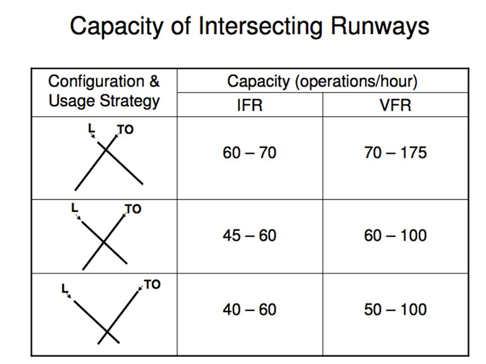
Intersecting Runway It becomes necessary to use this configuration when winds are blowing in more than one direction. When the winds are light both runways can be used. When the winds are strong only one runway can be used. Capacity depends on the location of the intersection point and the runway-use-strategy. The farther the intersection is from the takeoff end of the runway and the landing threshold, the lower is the capacity. Highest capacity is achieved when the intersection is close to the takeoff end and the landing threshold.

54
Intersecting Runway Airport

56
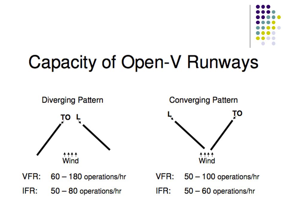
Open-V Runway Runways in divergent directions which do not intersect are referred to as open-V runways. When the winds are blowing in different directions, if the layout of the land permits, this configuration is preferred to intersecting runways. Both the runways can be operated only when the winds are light.• The runway-use-strategy where in the operations are away from the “V” yields highest capacity.

58
Runway Components

59
Clearway

60
Stopway

61
Runway Safety Area

62
Taxiway System The movement of aircrafts to and from the runways and the terminal/cargo, and parking areas is provided by a system of taxiways. This system of taxiways includes Entrance and exit taxiways Parallel taxiways Bypass taxiways Connecting or transverse taxiways Apron taxiways and taxi-lanes.

63
Exit Taxiways These are taxiways provided at appropriate locations along the length of runway so that the landing aircrafts can maneuver out of the runway minimising their runway occupancy time. Right angled exit taxiways: These are exit taxiways placed at right angles to the runway. When the design peak hour traffic is less than 30 operations (landings and takeoffs), a properly located right- angled exit taxiway will achieve an efficient flow of traffic. High speed exit taxiways: These exit taxiways are placed at acute angle to the runway and are designed to provide high exit (turnoff) speeds. These high speed exit taxiways when properly designed in terms of their number, location and exit speed can enhance the capacity of the runway.
, a properly located right- angled exit taxiway will achieve an efficient flow of traffic. High speed exit taxiways: These exit taxiways are placed at acute angle to the runway and are designed to provide high exit (turnoff) speeds. These high speed exit taxiways when properly designed in terms of their number, location and exit speed can enhance the capacity of the runway.")
66
Taxiways Intersection Design

67
Entrance & Parallel Taxiways
Entrance Taxiway: Entrance taxiways provide access to the takeoff end of the runway for the departing aircrafts and it also serves as the final exit taxiway for landing aircrafts on a bidirectional runway. It is normally in the form of an “L” taxiway intersection with a right angle connection to the runway. Parallel Taxiway: The taxiway running parallel to the runway connecting all the exit and entrance taxiways is called parallel taxiway.

69
Dual Parallel Taxiway Entrance

70
Cross overtaxiway

71
Bypass Taxiway As an alternative to holding bay a bypass taxiway parallel to the entrance taxiway leading to the runway end are generally provided. When a preceding aircraft is not ready for takeoff and blocks the entrance taxiway, other aircrafts in the queue can use the bypass taxiway.• Bypass taxiways provide flexibility in runway use by permitting ground maneuvering of steady streams of departing airplanes

73
Dual Parallel Taxiway Entrance with Bypass

74
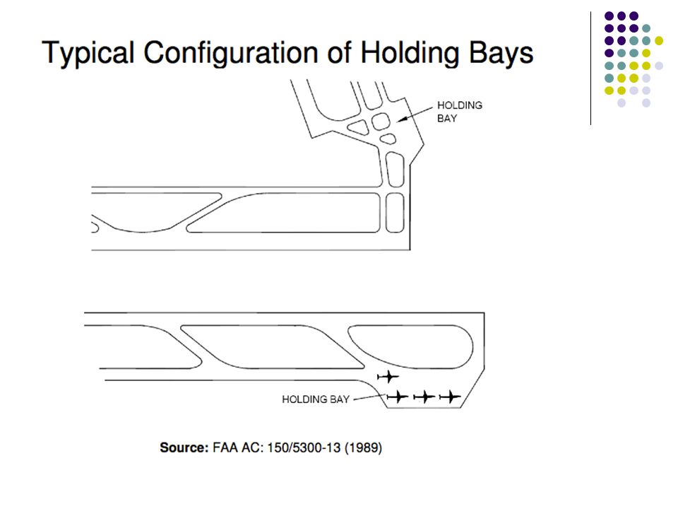
Holding Bay The designated place located adjacent to the ends of runways to allow check of aircraft instruments and engine operation prior to takeoff in the case of piston engine aircrafts and to enable all other aircrafts to wait for takeoff clearance from ATC. These are also referred to as run-up or warm-up pads. Due to adverse weather conditions enroute or at the destinations, certain aircrafts may have to be delayed while others are allowed to proceed with takeoff. Holding bays are useful in such situations for aircrafts to bypass one another. As per FAA guidelines a holding bay should be provided when runway operations reach a level of 30 per hour. A holding bay should be designed normally to accommodate two to four aircrafts and with enough space for cleared aircrafts to bypass the parked ones.

76
Taxiway Configuration

78
Transverse Slope

79
A slope at Runway and Taxiway

80
Airplane Bridge

81
Cross-section bridge and roadway

82
Jet Blast-Deflector

83
Parallel Taxiway Operation

84
Lane Width

85
Apron Taxiway and Taxilanes
Taxiway located on the periphery of an apron intended to provide a through taxi route across apron is referred to as apron taxiway. Taxilanes provide access from apron taxiways to airplane parking positions (gates). Taxilanes are located outside the movement area.
. Taxilanes are located outside the movement area.")
86
Fillet Design

87
See You in the Next Lecture
Thank You See You in the Next Lecture

Similar presentations


 2 November 2011 Helen Gannon Aviation.>")


 Saulo Da Silva>")

 Saulo Da Silva>")
 taking all reasonable steps to fully exploit the existing capacity of the air navigation system; b) developing plans.>")


