Download presentation
Presentation is loading. Please wait.

1
An Adder A Subtractor

2
A and B are the inputs of the adder/ subtractor R is the output of the adder/ subtractor F is the control to tell it to add or subtract D is the status to tell us when it is done (or maybe something else?) Arithmetic Logic Unit
 Arithmetic Logic Unit")
3
A Flip Flop A 4 bit register

4
Decoder Add Subtract AND OR Add Subtract AND OR To ALU

6
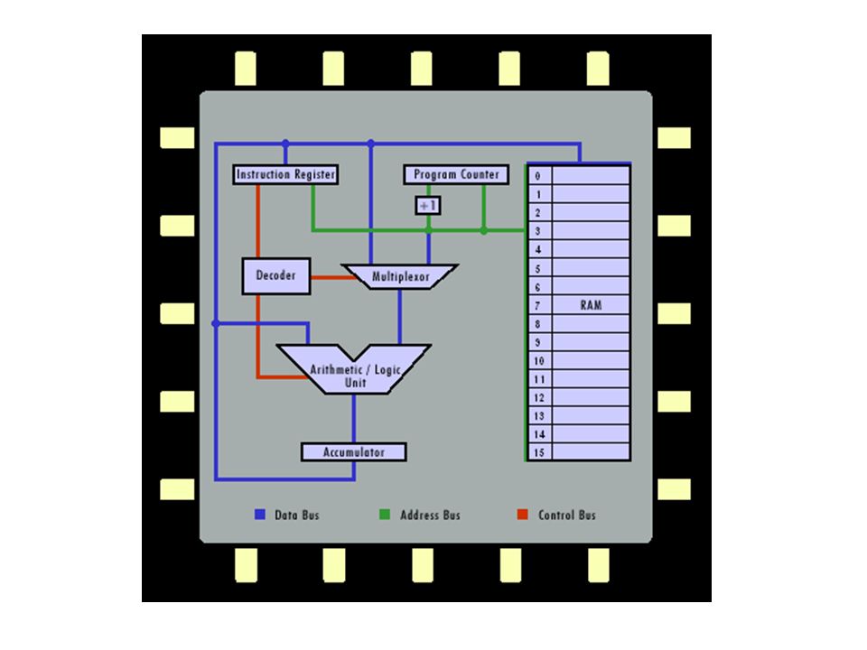
Op-codeMnemonicFunctionExample 001LOAD Load the value of the operand into the Accumulator LOAD 10 010STOREStore the value of the Accumulator at the address specified by the operandSTORE 8 011ADDAdd the value of the operand to the AccumulatorADD #5 100SUBSubtract the value of the operand from the AccumulatorSUB #1 101EQUAL If the value of the operand equals the value of the Accumulator, skip the next instruction EQUAL #20 110JUMP Jump to a specified instruction by setting the Program Counter to the value of the operand JUMP 6 111HALTStop executionHALT A simple machine language

7
#Machine codeAssembly codeDescription 0001 1 000101LOAD #5 These two operations set the count value to five 1010 0 001111STORE 15 2001 1 000000LOAD #0Initialize the count to zero 3101 0 001111EQUAL 15 Test to see if count is complete; if yes, skip next instruction and go to instruction 5; if no, go to next instruction 4110 1 000110JUMP #6Set Program Counter to 6 5111 0 000000HALT Stop execution 6011 1 000001ADD #1Increment the count in the Accumulator 7110 1 000011JUMP #3Set Program Count to 3.

8
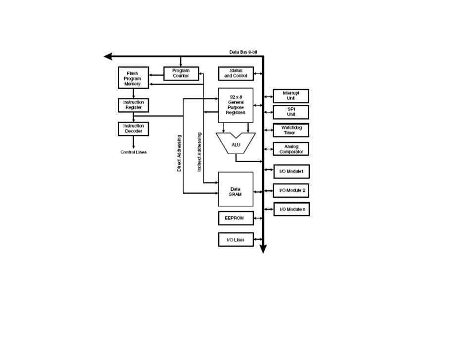
Von Neumann Architecture Harvard Architecture

10
Atmel Registers Note: R0 to R15 will not work with some instructions

11
Status Register I – Global Interrupt enable flag, must be set for interrupts to work T – Bit copy storage, used with BST and BLD H – Half carry flag, detects carry from lower nibble S – Sign flag, exclusive OR between N flag and V flag V – Two’s complement overflow flag N – Negative flag, result of an operation is negative Z – zero flag, result of an operation is zero C – Carry flag, indicates an overflow after count reaches 255

Similar presentations


 Example of program execution 1. instruction B25 8 Op-code B means to change the value of the program counter if the contents of the indicated register.>")


>")


 basis. It reverses the order that data arrives and is.>")


