Download presentation
Presentation is loading. Please wait.

1
Model Computer CPU Arithmetic Logic Unit Control Unit Memory Unit
Input/ Output Unit CPU Data Bus

2
Control Unit Arithmetic Logic Unit Memory Unit Input/ Output Unit MAR
Instruction Decoder PC Arithmetic Logic Unit Memory Unit Input/ Output Unit IR

3
Memory Unit Arithmetic Logic Unit Control Unit Input/ Output Unit MAR
Address Decoder MAR Main Store Arithmetic Logic Unit Control Unit Input/ Output Unit MDR

4
Arithmetic/Logic Unit
Control Unit Main Memory Input/ Output Unit SR ACC

5
Model Computer MAR Instruction Decoder PC SR ACC IR MDR
Address Decoder MAR Instruction Decoder PC SR ACC IR MDR

6
Registers A register is a single storage unit where data is stored temporary for a special purpose MAR holds the address of the memory location to be accessed MDR holds the data item read from or written to the specified memory location

7
Registers PC holds the address of the next instruction to be fetched from the main store IR holds the current instruction fetched from the main store while it is being decoded

8
Registers ACC holds the data item to be processed or the results of the most recent operations in the ALU SR holds a set of condition flags which describe the status of the most recent operation carried out by the ALU

9
Programming the CPU 00001 : Load the contents in memory location into the accumulator 00010 : Store the contents in the accumulator in the memory location 11101

10
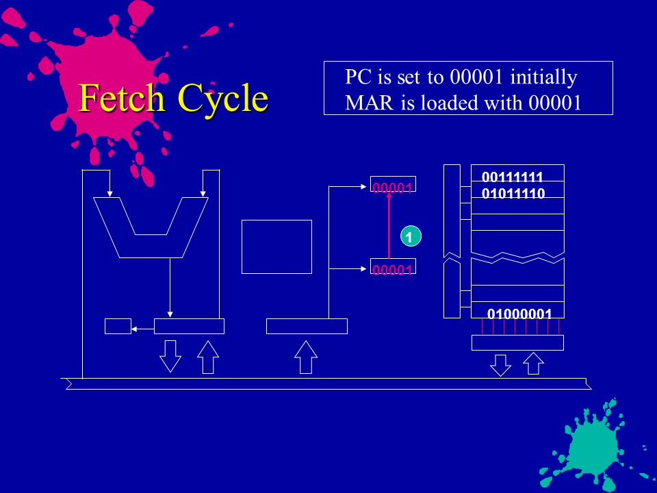
Fetch Cycle PC is set to 00001 initially MAR is loaded with 00001
00001 1 00001
11
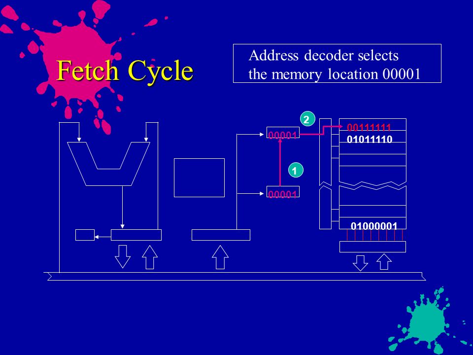
Fetch Cycle Address decoder selects the memory location 00001 2
00001 1 00001
12
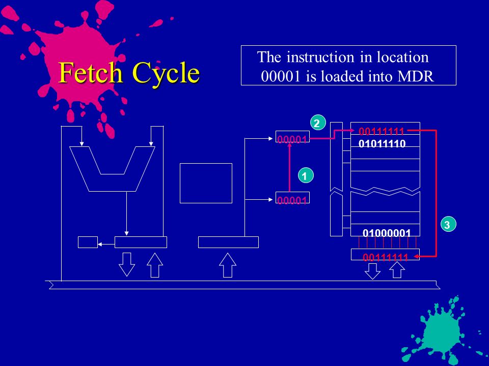
Fetch Cycle The instruction in location 00001 is loaded into MDR 2
00001 1 00001 3
13
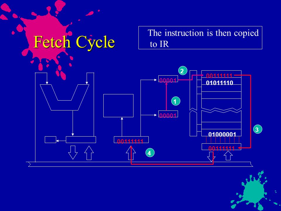
Fetch Cycle The instruction is then copied to IR 2 00111111 00001
1 00001 3 4
14
Execution Cycle PC is set to 00010 The instruction is decoded 00111111
00001 LDA 5 00010

15
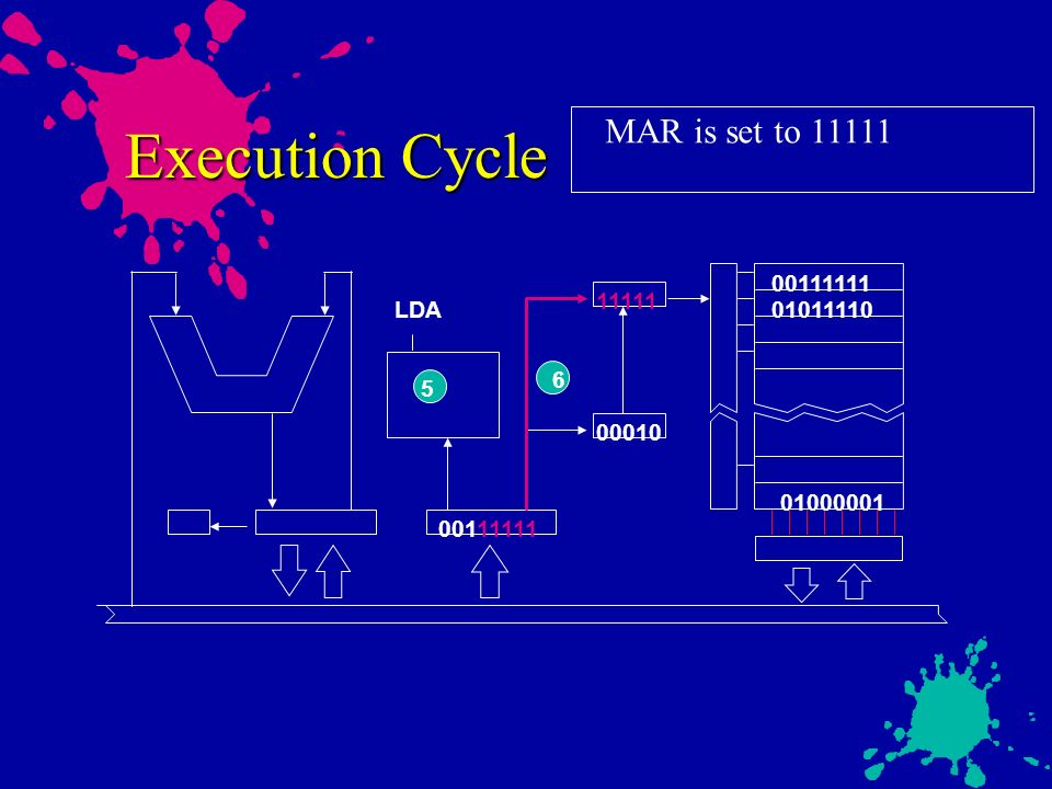
Execution Cycle MAR is set to 11111 00111111 11111 LDA 01011110 6 5
00010
16
Execution Cycle The address decoder selects the location 11111 7
11111 LDA 6 5 00010

17
Execution Cycle The data in location 11111 is loaded into MDR 7
11111 LDA 6 5 00010 8

18
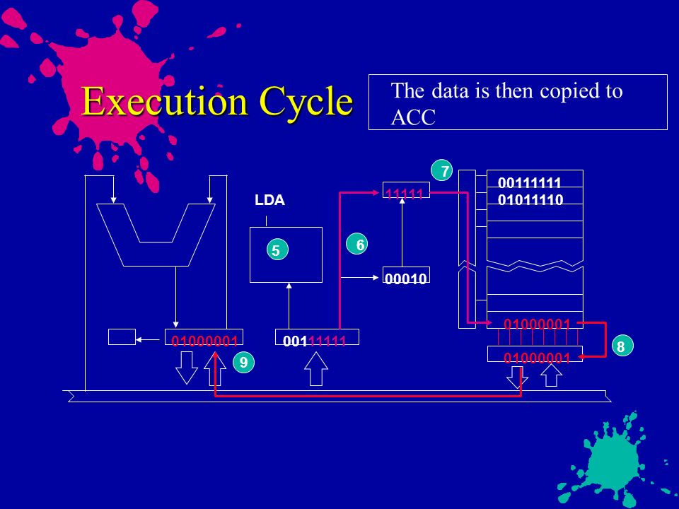
Execution Cycle The data is then copied to ACC 7 00111111 11111 LDA
6 5 00010 8 9
19
Fetch Cycle 00010 1 00010

20
Fetch Cycle 2 00010 1 00010

21
Fetch Cycle 2 00010 1 00010 3

22
Fetch Cycle 2 00010 1 00010 3 4

23
Execution Cycle 00010 STA 5 00011

24
Execution Cycle 11110 STA 6 5 00011

25
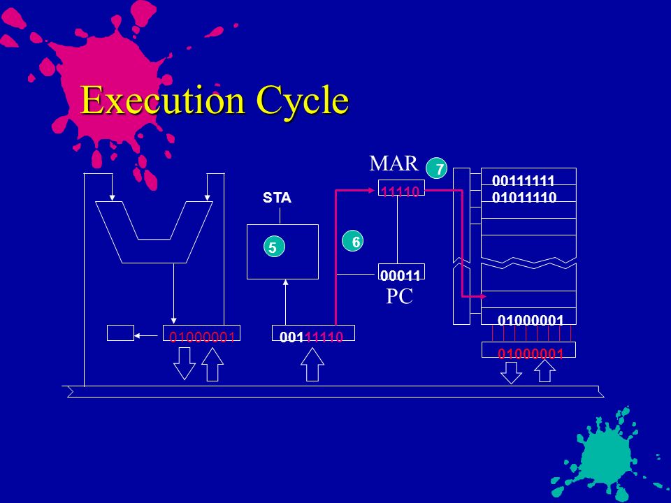
Execution Cycle MAR PC 7 00111111 11110 STA 01011110 6 5 00011
26
Execution Cycle 7 11110 STA 6 5 00011 8

27
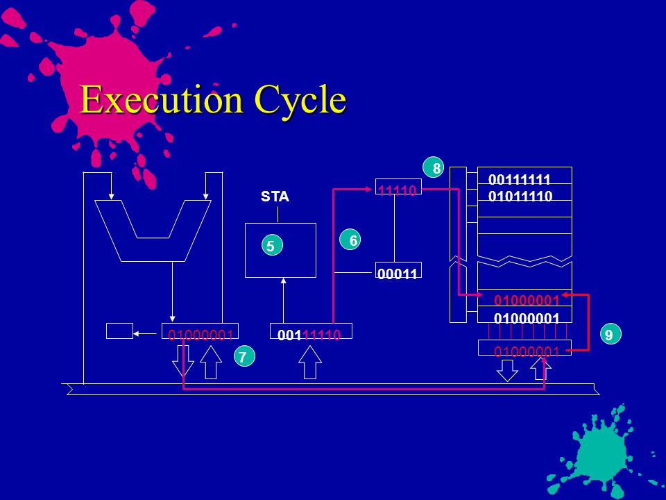
Execution Cycle 8 11110 STA 6 5 00011 9 7
28
SMC Instruction Set LDA load accumulator with memory
STA store accumulator in memory ADD add memory to accumulator SUB subtract memory from accumulator DEC decrement memory by 1 JMP unconditional jump BNE branch if negative STP stop

29
SMC Instruction Set LDA LoaD Accumulator with memory
STA STore Accumulator in memory ADD ADD memory to accumulator SUB SUBtract memory from accumulator DEC DECrement memory by 1 JMP unconditional JuMP BNE Branch if NEgative STP SToP

30
Fetch/Execution Cycle
Address in PC is sent to MAR Address decoder interpret the address in MAR and locate the specified memory location Control signal ( read ) is issued Contents in specified location are deposited into MDR Contents is then sent to IR Execute the instruction held in IR
 is issued. Contents in specified location are deposited into MDR. Contents is then sent to IR. Execute the instruction held in IR.")
31
Example program #1 00001 LDA 11111 00010 ADD 11110 00011 STA 11101
Address Instruction 1 LDA 11111 ADD 11110 STA STP 2 3 4

32
Example program #2 00001 LDA 11111 00010 SUB 11110 00011 BNE 00110
Address Instruction 1 LDA 11111 SUB 11110 BNE 00110 LDA 11111 JMP LDA 11110 STA STP 2 3 4 5 6 7 8

Similar presentations


>")
. It is called brain or heart of the.>")


>")
 – 5 bits (size of addresses) −Instruction.>")


>")