Download presentation
Presentation is loading. Please wait.

1
Microprocessors

2
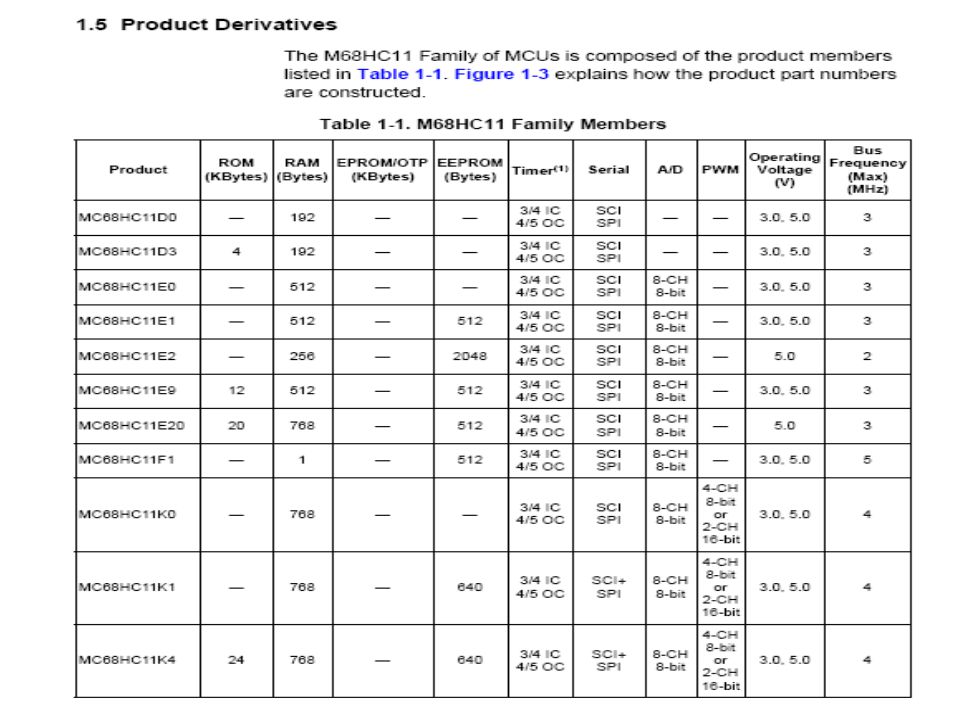
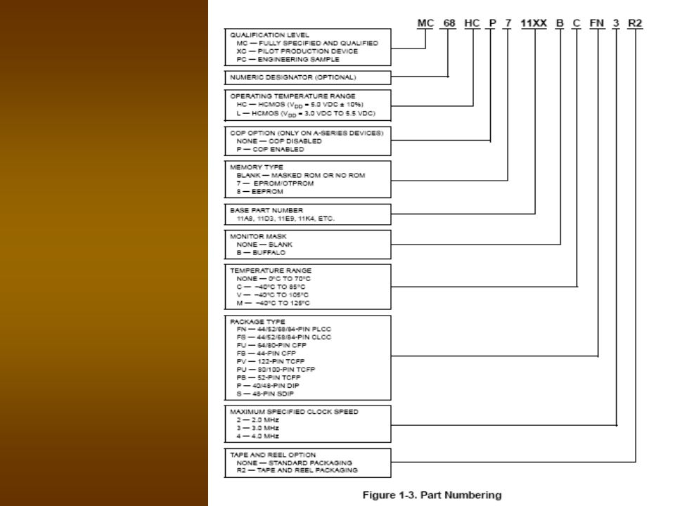
Functions of 68HC11 Microprocessor
Providing tuning and control signal for all elements of microcomputer Fetching instruction and data from memory Transferring data from memory Decoding instruction Performing arithmetic and logic operations called for by instructions Responding to I/O generated control signals such as reset and interrupt

3
68 HC MPU 5 16 bit registers 2 8 bit accumulators
8 bit condition code registers Control bus signals are expandable

4
Timing and control section
Control Bus signal AS signal E clock Reset

5
Functions of reset Fetches the content of ROM address FFFE and loads into PCH Fetches the content of ROM address FFFF and load it into PC1 so that (PC) is now 2AC6 Begin fetching and executing instruction at address 2AC6
 is now 2AC6. Begin fetching and executing instruction at address 2AC6.")
6
Microprocessor common function
Initialize MPU registers Initialize I/O device control registers Perform test on system RAM Check status of I/O devices Send messages to output devices

7
Instruction register When the MPU fetches an instruction word from memory it sends to the IR

8
Program Counter (PC) Contains in the memory address of the next instruction code that the MPU is to fetch.
 Contains in the memory address of the next instruction code that the MPU is to fetch.")
9
Accumulator Register that takes part in most of the operations performed by the ALU It is also the register in which the result are being placed after most ALU operations The source of the operand and destination of the result

10
Data Address Register Memory address register
Address latching register Used when executing ADD instruction

11
General Purpose register
GPR the accumulators can perform the function of a general purpose register in many programming situations.

12
Common GPR instruction access codes
Load GP from memory [M] > [GP] Store GP in memory [GP] > [M] Transfer contents of one GP register to another GP register : [GP1] > [GP2] Increment GP by 1: [GP +1 ] > [GP] Decrement GP by 1: [GP-1] > [GP]

13
If [GP] not = 0 branch back to 2
This set [GP] = COUNT Start 1 Load [GP] with value = COUNT Fron the memory Program Loop 2 Instruction Sequence to be Executed a number of times = COUNT 3 Decrement [GP] [GP -1] > [GP] If [GP] not = 0 branch back to 2 4 Is [GP] = 0? Yes 5 If [GP] =0 go to the next instruction in sequence Next portion of program
![If [GP] not = 0 branch back to 2](http://slideplayer.com/slide/3252913/11/images/13/If+%5BGP%5D+not+%3D+0+branch+back+to+2.jpg "This set [GP] = COUNT. Start. 1. Load [GP] with value = COUNT. Fron the memory. Program Loop. 2. Instruction Sequence to be. Executed a number of times. = COUNT. 3. Decrement [GP] [GP -1] > [GP] If [GP] not = 0 branch back to Is [GP] = 0 Yes. 5. If [GP] =0 go to the next instruction in sequence. Next portion of. program.")
14
Index register 68HC11 has two 16 bit index register (index register Y and index register X) Similar to general purpose register Its operation is called index addressing It holds address base C for X and Y index register

15
Offset instruction illustration for register X
Address Instruction code Mnemonic Description C000 A6 LDAA $04,X Load accumulator A from address [X]+04. C001 04 Offset byte Effective Address = offset + [X] = 04 + C450 = C454

16
Y register instruction illustration
Address Instruction code Mnemonic Description C000 18 LDAA $04,Y Load accumulator A A6 from address [Y]+04. C001 04 Offset byte Effective Address = offset + [Y] = 04 + C450 = C454

17
Important process during the operation
Accumulator A and B are cleared to zero before any ADD operation occurs Index register [X] is initially loaded with the number 2067 Accumulator B is initially loaded with 07 which the number of memory locations to be added. ACCB is being used to count down the number of times that blocks 5-8 are executed Blocks 5-8 are executed a total of seven times before ACCB is decrement to 00 program goes to block 9 to store the final sum in memory location 2068 The ADD operation (block 5) are executed using data from different address each time starting with 2067 and ending with 2061.this means the data is now loaded to the accumulator
 are executed using data from different address each time starting with 2067 and ending with 2061.this means the data is now loaded to the accumulator.")
18
Start 1 Clear [ACCA] 2 Clear [ACCB] 3 Load [X] with Value 2067 4 Load [ACCB] with value 07 Add data stored at address [X] +00 to [ACAA] 5 Decrement [X] 6 9 7 Decrement ACCB No 10 Store [ACCA] in memory location 2068 Is [ACCB]=0? HALT 8
![Start 1. Clear [ACCA] 2. Clear [ACCB] 3. Load [X] with Value Load [ACCB] with value 07.](http://slideplayer.com/slide/3252913/11/images/18/Start+1.+Clear+%5BACCA%5D+2.+Clear+%5BACCB%5D+3.+Load+%5BX%5D+with+Value+Load+%5BACCB%5D+with+value+07..jpg "Add data stored at. address [X] +00 to [ACAA] 5. Decrement [X] Decrement ACCB. No. 10. Store [ACCA] in. memory. location Is [ACCB]=0 HALT. 8.")
19
Condition Code register
Consist of individual bits Each bits is called Flags This is the 68HC11code register b7 b6 b5 b4 b3 b2 b1 b0 S X H I N Z V C

20
Condition Code functions
C – Carry flag reflects the carry status of arithmetic operation. V – the overflow use to indicate overflow whenever signed numbers are being added or subtracted Z – zero flag is automatically set to 1 N – negative used to indicate any sign result of any arithmetic data manipulation I- interrupt mask flag is used to indicate effects on the IRQ H – Half carry flag is change only by addition instruction X – X interrupt mask used to indicate not XIRQ S – stop disable flag is used to prevent the stop instruction

21
Conditional branching
It examine the value of the zero flag If zero flag is = 0 The next instruction will be taken at a normal sequence If zero flag is = 1 The program will branch into new address for the next instruction If carry clear (BCC) or set booth will examine the carry flag
 or set booth will examine the carry flag.")
27
Two operands operators
Add Subtract

28
Accumulator and memory
instructions

29
Load, Store and transfer instruction

30
Arithmetic operation instruction

31
Continuation..

32
Multiply and divide instruction

33
Logical operation instruction

34
Shift and rotate instructions

35
Stack and index register instruction

36
Condition code register instruction

38
Branch instructions

Similar presentations


 – 5 bits (size of addresses) −Instruction.>")


 basis. It reverses the order that data arrives and is.>")