Download presentation
Presentation is loading. Please wait.

2
Image Receptors Film Construction, Film Handling, Cassette Construction, DarkRoom, Digital Imaging 1

3
IMAGE RECEPTORS Image Receptors Film Imaging Film Construction Cassette Construction Film Handling Darkroom Digital Imaging Cassette Digital Imaging Direct Digital Imaging 2

4
-REVIEW OF PRIMARY BEAM -FILM CONSTRUCTION -FILM HANDLING -CASSETTE CONSTRUCTION -DARKROOM 3

5
Review of Primary Beam 4

6
Primary Radiation exit from tube 100 % enters patient 1% of the exit radiation forms image on cassette below 1% of the exit radiation forms image on cassette below REMNANT Radiation- Attenuated Beam Scatter Radiation- Compton 5

7
Review of Primary Beam Exit radiation interacts with IMAGE RECEPTOR to capture the image. radiographic image- permanent record of radiation exposed in image receptor latent image -the undeveloped, unprocessed image formed by exit radiation 6

8
FIRST “FILM” Glass plates Break easily Difficulty in storage Expensive Cellulose acetate Highly flammable Easily torn 7

9
Today’s Modern Film 8

10
Film Sizes Standard “inches”: 8” x 10” 10” x 12” 11” x 14” 14” x 17” Metric: 18cm x 24cm 24cm x 30cm 30cm x 35cm 35cm x 43cm 9

11
X-ray Film Two basic parts: 1. Base 2. Emulsion and Topcoat 10

12
Film Construction - BASE Made of a polyester plastic Must be clear, strong, consistent thickness Tinted pale blue or blue-gray (reduces eye strain) Uniform lucency COATED ON 1 OR 2 SIDES WITH EMULSION 11
 Uniform lucency COATED ON 1 OR 2 SIDES WITH EMULSION 11")
13
Film Construction - EMULSION Film emulsion can be on one side or both sides of base (single emulsion / double emulsion) Protective overcoat layered on top of emulsion-topcoat, supercoat Emulsion is a gelatin containing the film crystals---THE HEART OF THE FILM 12
 Protective overcoat layered on top of emulsion-topcoat, supercoat Emulsion is a gelatin containing the film crystals---THE HEART OF THE FILM 12")
14
FILM construction- EMULSION Emulsion : Gelatin with silver halide crystals imbedded Single or double emulsion, coated on one or both sides of polyester base Topcoat: Protective layer AKA supercoat 13

15
14

16
15

17
16

18
Film Emulsion Made of mixture of gelatin & silver halide crystals Silver halide crystals made of silver bromide (90%) and silver iodide (10%) Photographically active layer – activated by light & radiation to create image 17
 and silver iodide (10%) Photographically active layer – activated by light & radiation to create image 17")
19
Emulsion Contents Gelatin- comprised of mostly bone, suspends grains (crystals) easily, easily penetrated by processing agents, can be varied in thickness Silver Halide Crystals- x-ray (silver iodide) and light sensitive (silver bromide) crystals, contains sensitivity speck that reacts to both light and x-ray, this is where latent image is formed, crystals are varying in size, shape, density 18
 easily, easily penetrated by processing agents, can be varied in thickness Silver Halide Crystals- x-ray (silver iodide) and light sensitive (silver bromide) crystals, contains sensitivity speck that reacts to both light and x-ray, this is where latent image is formed, crystals are varying in size, shape, density 18")
20
Emulsion 19

21
Film Film Types Specialty Films -mammo Fluoro Video Laser Screen Film Depends on both x- ray action and light action Thinner emulsion Direct Exposure Depends on direct action of xrays Thick emulsion 20

22
Film Film Characteristics Speed Ability of emulsion to respond, depends on crystal size, crystal number, emulsion thickness Resolution-detail Ability of emulsion to record fine detail, depends on crystal size, single or double emulsion Latitude The range of exposures over which the image receptor responds with the optical density in a diagnostically useful range Contrast High contrast film produces very black and white images, Film emulsion contain smaller silver halide grains with a relatively uniform grain size - Low contrast film is grayer, Film emulsion contains larger silver halide grains that have a wider range of sizes - Rare-earth phosphors often exhibit slightly higher contrast 21

23
Film Characteristics Speed – the response to photons, the size and # of crystals and the thickness of emulsion, also known as sensitivity Resolution – the detail seen, depends on the size of the crystals, single or double emulsion (PARALAX) Latitude-The range of exposures over which the film responds with the optical density in a diagnostically useful range - Can be thought of as the margin of error in technical factors -Relates to crystal size and distribution Contrast-High contrast film produces very black and white images, Film emulsion contain smaller silver halide grains with a relatively uniform grain size - Low contrast film is grayer, Film emulsion contains larger silver halide grains that have a wider range of sizes - Rare-earth phosphors often exhibit slightly higher contrast IMAGEIMAGE 22
 Latitude-The range of exposures over which the film responds with the optical density in a diagnostically useful range - Can be thought of as the margin of error in technical factors -Relates to crystal size and distribution Contrast-High contrast film produces very black and white images, Film emulsion contain smaller silver halide grains with a relatively uniform grain size - Low contrast film is grayer, Film emulsion contains larger silver halide grains that have a wider range of sizes - Rare-earth phosphors often exhibit slightly higher contrast IMAGEIMAGE 22")
24
Speed Speed – the response to photons, the size and # of crystals and the thickness of emulsion, also known as sensitivity 23

25
Amount of Crystals More silver halide crystals = faster film Less silver halide crystals= slower film 24

26
Resolution- detail Resolution – the detail seen, depends on the size of the crystals, single or double emulsion (PARALLAX) 25
 25")
27
Parallax 26

28
PARALLAX –PARALLAX – each emulsion has an image single image each film has 2 emulsions creating overlapped – edges and a less sharp image Can you name the layers in this image? 1 1 2 2 3 3 4 27
29
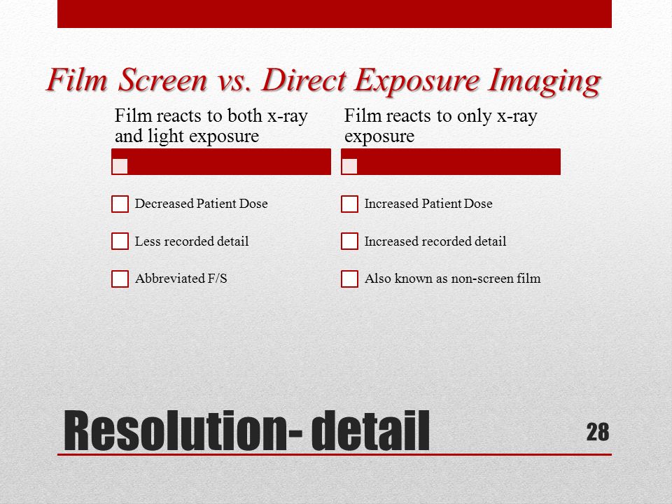
Resolution- detail Film Screen vs. Direct Exposure Imaging Film reacts to both x-ray and light exposure Decreased Patient Dose Less recorded detail Abbreviated F/S Film reacts to only x-ray exposure Increased Patient Dose Increased recorded detail Also known as non-screen film 28

30
Line pair resolution test: How many line pairs do you see? What kind of film would Sample A be? What kind of film would Sample B be? 29

31
Film Handling Handling and Storage of Films 30

32
X-ray Film Sensitivity Light X-rays Gamma Rays Gases Fumes Heat Moisture Pressure Static Electricity Age So what happens?? 31

33
Film Fog……..Unintended uniform optical density on a radiograph, get a long scale of contrast Artifacts……any unintended positive or negative image on the image receptor not caused by the exit beam, does not contribute to diagnostic image 32

34
Film Storage Clean, dry location 40 – 60 % Humidity 70 º Fahrenheit Away from chemical fumes Safe from radiation exposure Standing on edge Expiration date clearly visible 33

35
34

36
35

37
36

38
Cassette Construction 37

39
CASSETTES FUNCTION Protect film from exposure to light Protect film from bending and scratching during use. May contain intensifying screens, keeps film in close contact to screen during exposure. 38

40
Cardboard Cassettes Direct x-ray exposure to film: Requires 25 to 400 times more radiation to create an image on the film Better detail than film screen (no blurring of image from light) All exposure made from x-ray photons Very large dose to the patient 39
 All exposure made from x-ray photons Very large dose to the patient 39")
41
FILM CASSETTE or FILM HOLDER The CASSETTE is used to hold the film during examinations. It consist of front and back intensifying screens, and has a lead (Pb) backing. The cassette is light tight 40
 backing. The cassette is light tight 40.")
42
Cassette Features - Front Exposure side of cassette is the “front”. Has the ID blocker (patient identification) Made of radiolucent material Intensifying screen mounted to inside of front. 41
 Made of radiolucent material Intensifying screen mounted to inside of front. 41.")
43
FILM ID PRINTER ID blockerID blocker 42

44
Cassette Features - Back Back made of metal or plastic Inside back is a layer of lead foil – prevents backscatter that could fog the film Inside foil layer is a layer of padding – maintains good film/screen contact Back intensifying screen mounted on padding 43

45
Screen Construction Polyester plastic base – support layer Phosphor layer – active layer Reflective layer – increases screen efficiency by redirecting light headed in other directions Protective coating 44

46
Intensifying screens 45

47
Intensifying Screens Flat base coated with fluorescent crystals called phosphors Active layer- (phosphors) give off light when exposed to photons (x- rays) 46
 give off light when exposed to photons (x- rays) 46")
48
Intensifying Screens Phosphors RARE EARTH – (emits green light) Developed in 1980’s Most efficient Most common in use today CALCIUM TUNGSTATE (blue light) Not as efficient Not used as often 47
 Developed in 1980’s Most efficient Most common in use today CALCIUM TUNGSTATE (blue light) Not as efficient Not used as often 47")
49
Rare Earth Screens two times faster than calcium tungstate Gadolinium Lanthanum Yttrium Found in low abundance in nature 48

50
49

51
INTENSIFYING SCREENS DISADVANTAGES: less detail than direct exposure (but detail better with rare earth than calcium tungstate screens) ADVANTAGES: Reduce patient exposure Increase x-ray tube life 50
 ADVANTAGES: Reduce patient exposure Increase x-ray tube life 50")
52
Intensifying Screen & Film Cross Section 51

53
52

54
The light photons are emitted by phosphor crystals. These crystals are significantly larger than the silver halide crystals in the film Screen reduces image sharpness Exams requiring extremely fine detail use screens with small crystals. 53

55
Spectral Sensitivity OR SPECTRAL MATCHING Film is designed to be sensitive to the color of light emitted by the intensifying screens Blue – UV light sensitive film – CALCIUM TUNGSTATE screens Green, Yellow-Green light sensitive film - RARE EARTH screens 54

56
Film and Screen Crystals 55

57
56

58
57

59
58

60
Screen Speed Efficiency of a screen in converting x-rays to light is Screen Speed. 59

61
Screen Speed Greater efficiency less exposure - faster Standard screen speed class of 100 200 screen speed is twice as fast Speeds for routine work: 200 – 800 Speeds for high detail: 50 - 100 60

62
61 Good use of detailed screens and high contrast film

63
Image creation 1% of x-ray photons that leave patient Interact with phosphors of intensifying screens 100’s of light photons created to make image on film Light photons expose silver halide crystals in the film emulsion – Turn black metallic silver after procession 62

64
Care of Screens Common Causes of Poor Screen Contact worn contact felt loose hinges, latches warped screens cause by moisture warped cassette front cracked cassette frame foreign matter under screen 63

65
POOR SCREEN CONTACT NO GAPS- FOAM BACKING HELPS TO PLACE INTENSIFYING SCREENS IN DIRECT CONTACT WITH THE FILM IF GAPS MORE LIGHT CAN BE EMITTED IN SPACE, CAUSING THE IMAGE TO BE OF POOR DETAIL 64

66
65

67
66

68
DARKROOM 67

69
DARKROOM Light tight, lockable door Safe light Clean, uncluttered counter space Film bin with opened boxes of film Processor Pass Box Unopened boxes of film 68

70
Process of X-ray Image 69 FILM X-RAY LATENT IMAGE PROCESSOR MANIFEST IMAGE

71
PROCESSOR 70 Feed tray Developer Fixer Wash Dryer Latent Image Manifest Image

72
71 Common type of film processer Can process films as fast as 90seconds

73
72 Schematic of Film Processor Feed tray-#10 Developer-#12 Fixer-#13 Wash-#14 Dryer#19,15 Receiving bin-last arrow

74
73 Developing is the stage where the latent image is converted to the manifest (visible) Image. PhenidoneDeveloping Agent HydroquinoneDeveloping Agent Sodium CarbonateActivator Potassium BromideRestrainer Developing Agents help change ionic silver to metallic silver (black). Silver ion is said to be reduced. Only crystals that contain the latent image are reduce to metallic silver.
. Silver ion is said to be reduced. Only crystals that contain the latent image are reduce to metallic silver..")
75
74 The stage of processing where the film gets treated so that the image will not fade but will remain permanently is called fixing. Acetic acidactivator Ammonium thiosulfate(hypo)clearing agent Potassium alumhardener Sodium sulfitepreservative Watersolvent Fixing the film CLEARS the film of all undeveloped silver halides. It is important to stop the developing process because with time, all the ionic silver will be reduced to metallic silver, thus ruining our image. Our latent image must be processed in a timely fashion or we will have image degradation.
clearing agent Potassium alumhardener Sodium sulfitepreservative Watersolvent Fixing the film CLEARS the film of all undeveloped silver halides. It is important to stop the developing process because with time, all the ionic silver will be reduced to metallic silver, thus ruining our image. Our latent image must be processed in a timely fashion or we will have image degradation..")
76
75 The function of the wash cycle is to remove ANY residual chemicals from the film. Water is used as the washing agent. Failure to completely wash the residual chemicals could result in film fog, hypo retention, yellowing of films, fading of films, The final step of the processing is to dry the film before it leaves the processer. Failure to do so occasionally results in sticky films which eventually cause artifacts.

77
76 Replenishment Replenishment : As chemistry is used up by the processing of image, the proper chemical balance is needed to be maintained. As a film enters the first stages of processing, the replenishment system turns on and the chemistry in both developer and the fixer are added to as needed according to prescribed rates. Silver Recovery: Silver Recovery: As the latent image is developed into the manifest image, the unaffected silver halide crystals will be washed off. Each processor will have a silver recovery system in place. This is economically sound and environmentally helpful. It also helps prevent the processor from breaking down due to clogging of the system by metallic silver. $

78
Any Questions ?????? 77

Similar presentations