Download presentation
Presentation is loading. Please wait.

1
Technical Aspects: the machine the image
LeeAnn Pack DVM

4
Exposure settings: 4 components
kVp mAs Time Focal film distance (FFD) All can be changed alone or in combination
 All can be changed alone or in combination.")
5
Make it just right Make a film more black Make a film less black
Increase the kVp, mAs or time Decrease the FFD Make a film less black Decrease the kVp, mAs or time Increase the FFD

6
Questions to Ponder Is there adequate penetration of the part imaged?
How much contrast is needed on the film (some inherent?)? Is motion a strong possibility during the exposure? Does the tube move?
 Is motion a strong possibility during the exposure Does the tube move")
7
Inverse Square Law Decrease distance by ½ intensity is increased by 4 times Increase distance by ½ intensity is increased by 4 times Technical applications Radiation safety

8
Cassettes Contain single or double screen Plastic, cardboard, metal
Must be durable Film placed between the screens in the cassette Foam between cassette and screen Keeps out unwanted light

10
Intensifying Screens Absorb X ray photons and convert them to light
Reduces amount of radiation needed Contain phosphors Calcium tungstate blue light Rare earth phosphors green light More efficient

11
Screen Speed Determined by the efficiency of X ray absorption and conversion Thicker phosphor layer and larger crystal produce a greater amount of light faster Slow detail photonsresolution Medium par average Fast less resolution but not as many photons needed

12
Screen Speed/Resolution
100,200,400,800 Smaller number being a slower high resolution screen and the higher numbers are a faster screen Screen speed and resolution are inversely proportional

14
Screen Cleaning Keep free of debris Sharp white artifact
Screen cleaner Soft lint free cloth Never use soap and water Stand on end to dry

15
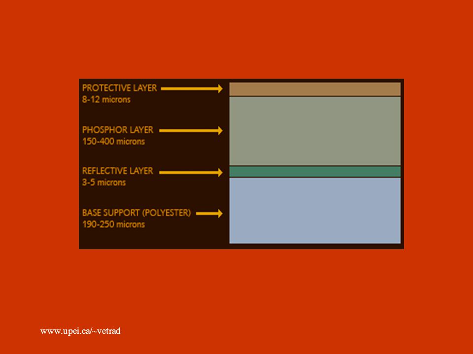
Radiographic Film Composition Base supports the emulsion – blue
Adhesive – base to emulsion Emulsion – gelatin with silver halide crystals which is sensitive to radiation Protective coat protects from damage during handlin and processing

17
Radiographic Films Single or double emulsion Light sensitivity
Film speed Film speed is inversely related to exposure needed to produce a given degree of blackness 50 speed is half as fast as a 100 speed

18
Radiographic Film Film latitude
Range of exposures which can be used to achieve an acceptable film density Wide range = high latitude Image contrast suffers Narrow range = low latitude Good image contrast

19
Radiographic Density Subject density Over exposed = film to black
Additive – thick parts absorb more Summation – know definition Relative What are the surroundings? Silhouette sign – know definition Over exposed = film to black Under exposed = film not black enough

20
Factors that affect film density
Subject density – we cant change this mAs – biggest factor kVp – increases the penetrability Distance – ISL Development time and temp Scatter and fog

21
Radiographic Contrast
Difference of densities of the different parts on the image Subject contrast Film contrast Scatter and fog

22
Turn that dial: Density
The rule kVp by 20% will double film density kVp by 16% will half film density Double mAs double density Half mAs half density Combos: Inc kVp by 20% and dec mAs by half Dec kVp by 16% and double mAs

23
Contrast Short scale lot of contrast few grey
High mAs and low kVp Long scale many shades of grey Low mAs and high kVp Low contrast = long scale = high latitude = low mAs = high kVp High contrast = short scale = low latitude = high mAs = high kVp

24
Magnification Enlargement of the image relative to the actual size
Causes loss of detail and blurring Subject film distance Dec SFD decreases magnification Focal film distance Inc FFD decreases magnification

25
Distortion Image which does not represent the true shape of the object
Unequal projection of an object Femurs Location of an object within the beam spine

26
Scatter radiation What is scatter? Scatter increases with:
Bounce around undergo numerous interactions Scatter increases with: Increased thickness of the patient Increased X ray beam energy Amount of patient exposed (collimate)
")
27
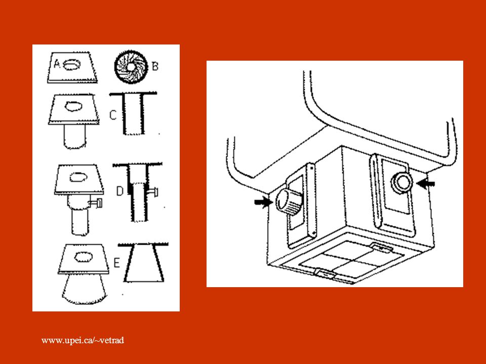
Beam Limiting Devices Smaller fields = less scatter and less radiation expsoure Cones, cylinders, shuttered collimators They do not shape the beam only exclude the part we don’t want to use Light to illuminate field

29
Filtration Inherent Added Polychromatic beam Reduces patient dose
Glass housing, oil and tub housing window Filter only low energy photons Added Aluminum filter Will not remove the high energy photons Polychromatic beam Reduces patient dose

30
Grids Used to keep scatter from hitting film
Perpendicular radiation gets through, off angle photons do not Used on parts > 10-11cm Film contrast is improved Required more X ray exposure

31
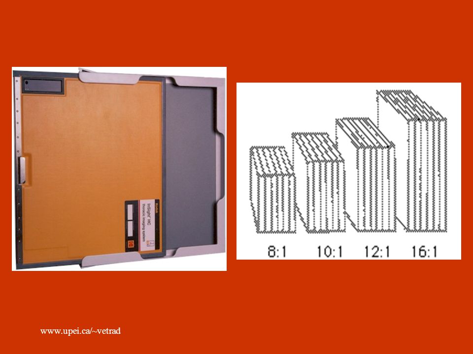
Grid ratio Height of lead strips:width between the strips
The higher the GR, the greater the ability of the grid to remove scatter 4:1 – 16:1 Lines per inch Good and bad

33
Grid Cutoff Grid must be precisely under the center of the central ray of the X ray beam along the central axis of the grid Know what the types of grid cutoff look like Bucky-Potter moving grid

34
Fog Light fog Storage fog Safelight fog Chemical fog

Similar presentations


![[Radiography] Technique - Exposure Factors](/5/1525033/big_thumb.jpg "[Radiography] Technique - Exposure Factors>")


