Download presentation
Presentation is loading. Please wait.

2
8086 and families

3
Features of 8086 16Bit Microprocessor : 8086 - 8086 is a 16bit processor. It’s ALU, internal registers works with 16bit binary word - 8086 has a 16bit data bus. It can read or write data to a memory/port either 16bits or 8 bit at a time - 8086 has a 20bit address bus which means, it can address up to 220 = 1MB memory location - Frequency range of 8086 is 6-10 MHz

4
8086 Architecture

5
Registers

7
8086 and 8088 Microprocessors 8086 announced in 1978; 8086 is a 16 bit microprocessor with a 16 bit data bus 8088 announced in 1979; 8088 is a 16 bit microprocessor with an 8 bit data bus Both manufactured using High-performance Metal Oxide Semiconductor (HMOS) technology Both contain about 29000 transistors Both are packaged in 40 pin dual-in-line package (DIP) Address lines A0-A7 and Data lines D0-D7 are multiplexed in 8088 – By multiplexed we mean that the same pysical pin carries an address bit at one time and the data bit another time Address lines A0-A15 and Data lines D0-D15 are multiplexed in 8086
 technology Both contain about transistors Both are packaged in 40 pin dual-in-line package (DIP) Address lines A0-A7 and Data lines D0-D7 are multiplexed in 8088 – By multiplexed we mean that the same pysical pin carries an address bit at one time and the data bit another time Address lines A0-A15 and Data lines D0-D15 are multiplexed in 8086")
9
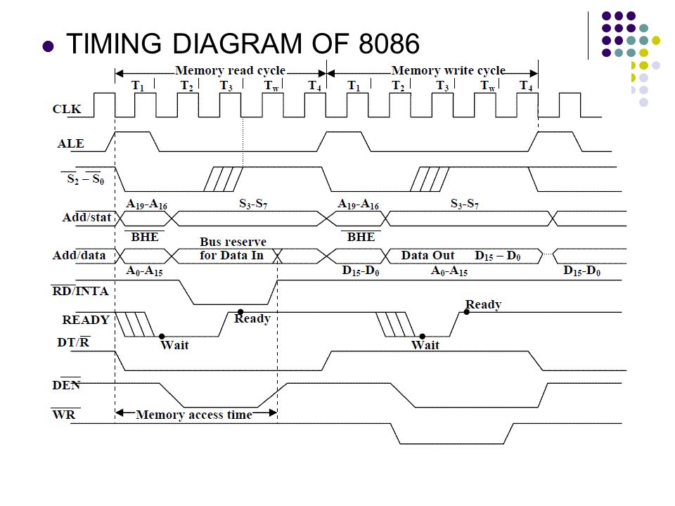
TIMING DIAGRAM OF 8086

10
Minimum-mode and Maximum-mode Systems 8088 and 8086 microprocessors can be configured to work in either of the two modes: the minimum mode and the maximum mode Minimum mode: – Pull MN/MX to logic 1 – Typically smaller systems and contains a single microprocessor Maximum mode – Pull MN/MX logic 0 – Larger systems with more than one processor

11
Minimum-mode and Maximum-mode Systems Signals common to both minimum and maximum systems

12
Minimum mode unique signals

13
8086 Minimum-mode block diagram

14
BASIC 8086 MINIMUM MODE SYSTEM CLK READY RESET 8284A CLOCK GENE- RATOR WAIT STATE GENERATOR MN/MX M/IO INTA RD WR DT/R DEN ALE AD0- AD15 A16-A19 8282 LATCH 8286 TRAN- CEIVER RAM 2142 2716 PROM PERI- PHERAL DATA ADDR/DATA ADDR

15
CLK M/IO ALE ADDR/ DATA ADDR/ STATUS RD/INTA READY DT/R DEN T1T2T3TWTW T4 A15-A0 A19-A16 RESERVED FOR DATA VALID D15-D0 MEMORY ACCESS TIME

16
CLK M/IO ALE ADDR/ DATA ADDR/ STATUS READY DT/R DEN T1T2T3TWTW T4 A15-A0 A19-A16 DATA OUT (D15-D0) WR
 WR")
17
Minimum Mode Interface Address/Data bus: 20 bits vs 8 bits multiplexed Status signals: A16-A19 multiplexed with status signals S3-S6 respectively – S3 and S4 together form a 2 bit binary code that identifies which of the internal segment registers was used to generate the physical address that was output on the address bus during the current bus cycle. – S5 is the logic level of the internal interrupt enable flag, s6 is always logic 0.

18
S4 S3 Address status 0 0 Alternate(relativeto ES segment) 0 1 Stack (relative to SS Segment) 1 0 Code/None (relative to CS segment or a default zero) 1 1 Data (relative to DS segment)
 0 1 Stack (relative to SS Segment) 1 0 Code/None (relative to CS segment or a default zero) 1 1 Data (relative to DS segment)")
19
Maximum mode unique signals

20
Maximum-mode interface circuit diagram (8086)
")
21
Maximum Mode 8086 System Continued…

22
Maximum Mode Interface For multiprocessor environment 8288 Bus Controller is used for bus control WR¯,IO/M¯,DT/R¯,DEN¯,ALE, INTA¯ signals are not available Instead: – MRDC¯ (memory read command) – MWRT¯ (memory write command) – AMWC¯ (advanced memory write command) – IORC¯ (I/O read command) – IOWC¯ (I/O write command) – AIOWC¯ (Advanced I/O write command) – INTA¯ (interrupt acknowledge)
 – MWRT¯ (memory write command) – AMWC¯ (advanced memory write command) – IORC¯ (I/O read command) – IOWC¯ (I/O write command) – AIOWC¯ (Advanced I/O write command) – INTA¯ (interrupt acknowledge)")
23
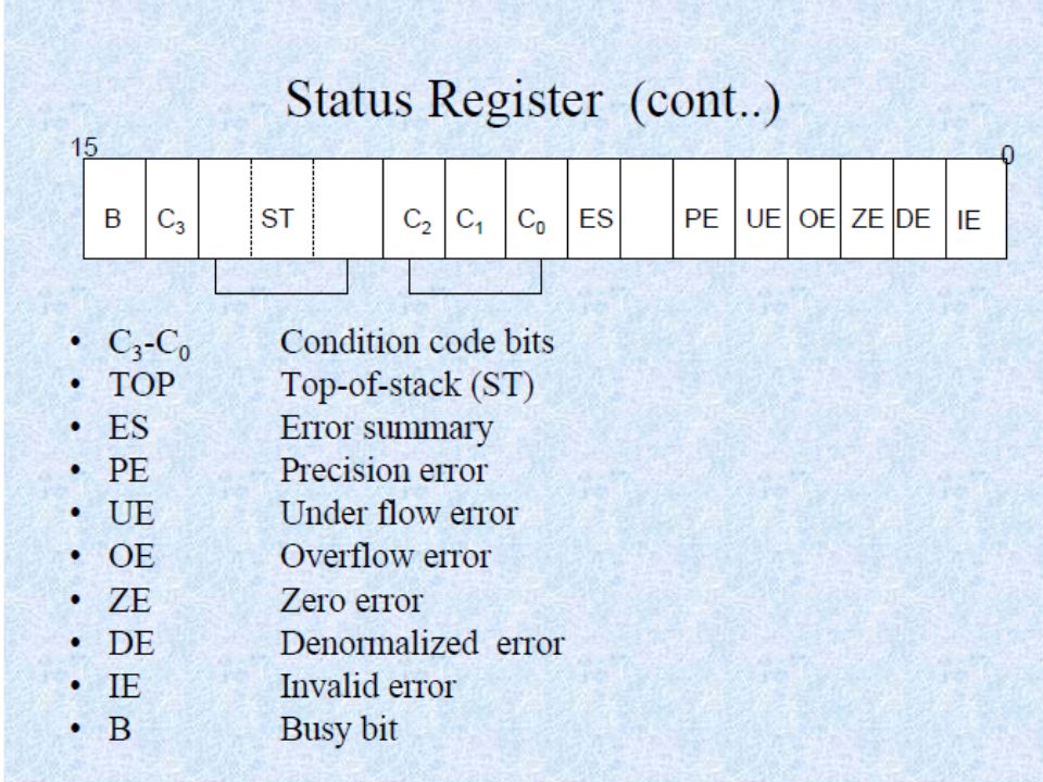
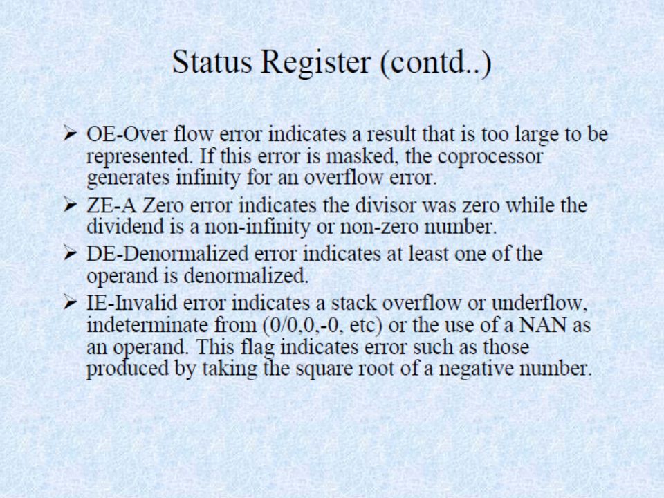
Status Bits They indicate the function of the current bus cycle. They are normally decoded by the 8288 bus controller

24
– The signals shown above are produced by 8288 depending on the state of S0, S1 and S2. DEN, DT/R¯ and ALE signals are the same as minimum-mode systems LOCK¯: when =0, prevents other processors from using the bus QS0 and QS1 (queue status signals) : informs about the status of the queue RQ¯/GT ¯0 and RQ¯/GT ¯1 are used instead of HOLD and HLDA lines in a multiprocessor environment as request/grant lines.
 : informs about the status of the queue RQ¯/GT ¯0 and RQ¯/GT ¯1 are used instead of HOLD and HLDA lines in a multiprocessor environment as request/grant lines..")
25
Memory Read timing in Maximum Mode Here MRDC* signal is used instead of RD* as in case of Minimum Mode S0* to S2* are active and are used to generate control signal.

27
Read Cycle of the 8086 - maximum mode

28
INTERRUPT The meaning of ‘interrupts’ is to break the sequence of operation.While the cpu is executing a program,on ‘interrupt’ breaks the normal sequence of execution of instructions, diverts its execution to some other program called Interrupt Service Routine (ISR).After executing ISR, the control is transferred back again to the main program.
.After executing ISR, the control is transferred back again to the main program.")
29
Interrupt Vector Table Type 0 POINTER (DIVIDE ERROR) Type 1 POINTER (SINGLE STEP) Type 2 POINTER (NON-MASKABLE) Type 3 POINTER (BREAK POINT) Type 4 POINTER (OVERFLOW) 010H 00CH 008H 004H 000H 16 bits CS base address IP offset
 Type 1 POINTER (SINGLE STEP) Type 2 POINTER (NON-MASKABLE) Type 3 POINTER (BREAK POINT) Type 4 POINTER (OVERFLOW) 010H 00CH 008H 004H 000H 16 bits CS base address IP offset")
30
03FFH Type 5 Reserved Type 31 (Reserved) Type 32 (Available) 03FCH 080H 07FH 0014H Reserved Interrupts (27) Type 255 (Available) Available Interrupts (224)
 Type 32 (Available) 03FCH 080H 07FH 0014H Reserved Interrupts (27) Type 255 (Available) Available Interrupts (224)")
31
Interrupt Vector Table INT Number Physical Address INT 0000000 INT 0100004 INT 0200008 : INT FF003FC

32
Example Find the physical address in the interrupt vector table associated with a) INT 12H b) INT 8H Solution: a) 12H * 4 = 48H Physical Address: 00048H ( 48 through 4BH are set aside for CS & IP) b) 8 * 4 = 20H Memory Address : 00020H
 INT 12H b) INT 8H Solution: a) 12H * 4 = 48H Physical Address: 00048H ( 48 through 4BH are set aside for CS & IP) b) 8 * 4 = 20H Memory Address : 00020H")
33
Functions associated with INT00 to INT04 (Exceptions) INT 00 (divide error) INT00 is invoked by the microprocessor whenever there is an attempt to divide a number by zero ISR is responsible for displaying the message “Divide Error” on the screen
 INT 00 (divide error) INT00 is invoked by the microprocessor whenever there is an attempt to divide a number by zero ISR is responsible for displaying the message Divide Error on the screen")
34
Ex1: Mov AL,82H;AL= 82 SUB CL,CL;CL=00 DIV CL;82/0 = undefined result EX2: Mov AX,0FFFH; AX = FFFFH Mov BL,2 ; BL=02 DIV BL; 65,535/2 = 32767 larger than 255 maximum capacity of AL

35
INT 01 For single stepping the trap flag must be 1 After execution of each instruction, 8086 automatically jumps to 00004H to fetch 4 bytes for CS: IP of the ISR

36
INT 02 (Non maskable Interrupt) 8086 NMI 5v When ever NMI pin of the 8086 is activated by a high signal (5v), the CPU Jumps to physical memory location 00008 to fetch CS:IP of the ISR assocaiated with NMI
 8086 NMI 5v When ever NMI pin of the 8086 is activated by a high signal (5v), the CPU Jumps to physical memory location to fetch CS:IP of the ISR assocaiated with NMI")
37
INT 03 (break point) A break point is used to examine the cpu and memory after the execution of a group of Instructions. It is one byte instruction whereas other instructions of the form “INT nn” are 2 byte instructions.

38
INT 04 ( Signed number overflow) There is an instruction associated with this INT 0 (interrupt on overflow). If INT 0 is placed after a signed number arithmetic as IMUL or ADD the CPU will activate INT 04 if 0F = 1. In case where 0F = 0, the INT 0 is not executed but is bypassed and acts as a NOP.

39
Example Mov AL, 64 Mov BL, 64 ADD AL, BL INT 0; 0F = 1 0100 0000 1000 0000 +64 +128 INT 0 causes the cpu to perform “INT 04” and jumps to physical location 00010H of the vector table to get the CS : IP of the ISR

40
HARDWARE INTERRUPTS NMI : Non maskable interrupts INTR : Interrupt request NMI INTR INTA 8086 Edge triggered Input Level triggered Input Response to INTR input

41
NMI: TYPE 2 Interrupt INTR: Between 20H and FFH Hardware Interrupts

42
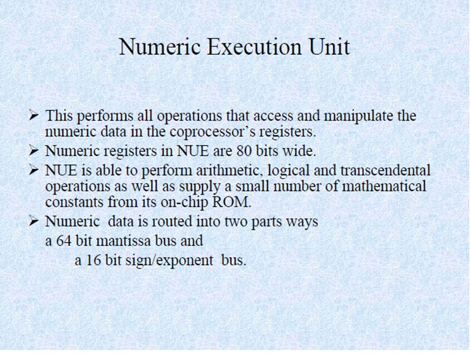
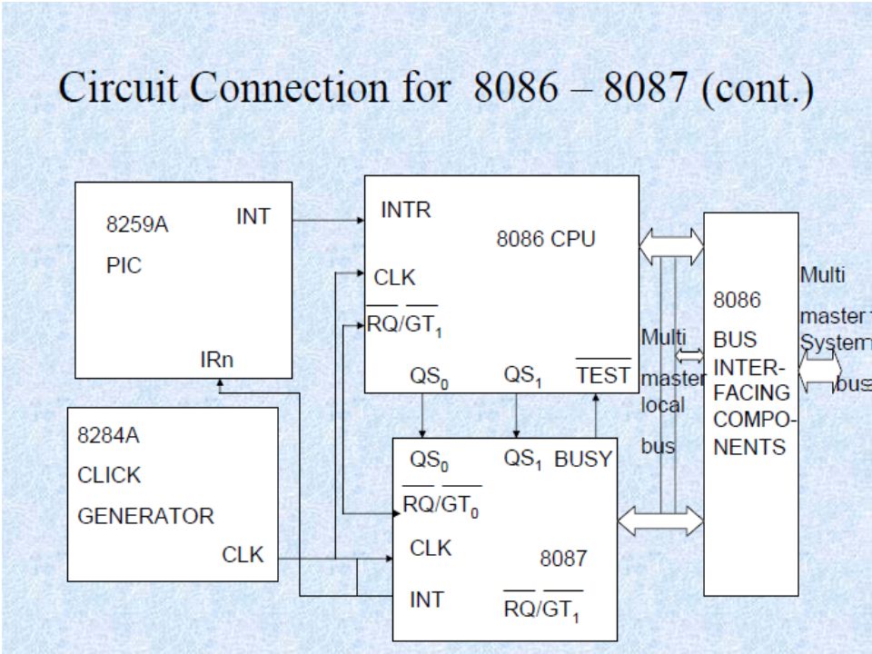
The Math Coprocessor:8087(Numeric Data Processor (NDP)) The 8086 performs integer math operations Floating point operations are needed, e.g. for Sqrt (X), sin (x), etc. These are complex math operations that require large registers, complex circuits, and large areas on the chip A general data processor avoids this much burden and delegates such operations to a processor designed specifically for this purpose -e.g. math coprocessor (8087) for the 8086 The 8086 and the 8087 coprocessors operate in parallel and share the busses and memory resources The 8086 marks floating point operations as ESC instructions, will ignore them and 8087 will pick them up and execute them
, sin (x), etc. These are complex math operations that require large registers, complex circuits, and large areas on the chip A general data processor avoids this much burden and delegates such operations to a processor designed specifically for this purpose -e.g. math coprocessor (8087) for the 8086 The 8086 and the 8087 coprocessors operate in parallel and share the busses and memory resources The 8086 marks floating point operations as ESC instructions, will ignore them and 8087 will pick them up and execute them.")
43
8087-MATH COPROCESSOR

44
ARCHITECTUTRE CONTROL UNIT EXECUTION UNIT

58
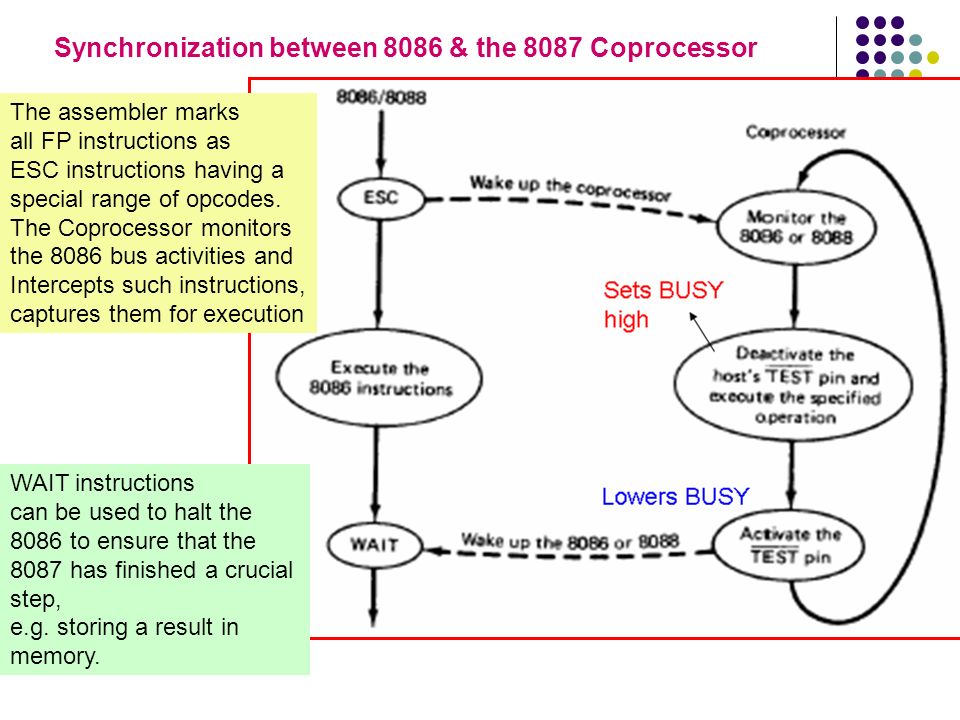
Synchronization between 8086 & the 8087 Coprocessor The assembler marks all FP instructions as ESC instructions having a special range of opcodes. The Coprocessor monitors the 8086 bus activities and Intercepts such instructions, captures them for execution WAIT instructions can be used to halt the 8086 to ensure that the 8087 has finished a crucial step, e.g. storing a result in memory.

59
Direct Memory Access (DMA) Direct Memory Access (DMA) - device other than processor controls transfer of data between memory and an I/O device – contrast with processor/memory accesses and I/O instructions A DMA controller, or DMAC, is specialized logic (processor) that is optimized for the task of transferring data between I/O devices and memory without involving main processor (CPU) A DMA channel is the set of control and data lines a DMA controller uses to perform the transfer of data a DMA controller can have multiple channels so DMA accesses can be performed for multiple devices (but only one at a time, and only for a set of similar devices)
 Direct Memory Access (DMA) - device other than processor controls transfer of data between memory and an I/O device – contrast with processor/memory accesses and I/O instructions A DMA controller, or DMAC, is specialized logic (processor) that is optimized for the task of transferring data between I/O devices and memory without involving main processor (CPU) A DMA channel is the set of control and data lines a DMA controller uses to perform the transfer of data a DMA controller can have multiple channels so DMA accesses can be performed for multiple devices (but only one at a time, and only for a set of similar devices)")
60
At minimum, a DMA operation needs the channel number (which I/O device requires the DMA), a beginning address in memory for the transfer, the number of bytes to transfer, and the direction of transfer (I/O to memory, or vice-versa) The processor kicks off the DMA activity with an ordinary I/O write to a control register in the DMA controller, then continues fetching and executing instructions as usual When DMA activity is finished, DMA controller interrupts the processor, resulting in execution of ISR for the DMAC DMAC more efficiently transfers data blocks between I/O device and memory than the CPU (why?) -- also, the CPU is freed to perform other tasks (overlapped or concurrent)
, a beginning address in memory for the transfer, the number of bytes to transfer, and the direction of transfer (I/O to memory, or vice-versa) The processor kicks off the DMA activity with an ordinary I/O write to a control register in the DMA controller, then continues fetching and executing instructions as usual When DMA activity is finished, DMA controller interrupts the processor, resulting in execution of ISR for the DMAC DMAC more efficiently transfers data blocks between I/O device and memory than the CPU (why ) -- also, the CPU is freed to perform other tasks (overlapped or concurrent)")
61
DMAC Connection

62
3 Modes of DMA Operation ByteBurst Block

63
Direct Memory Access (DMA) Operation of a DMA transfer
 Operation of a DMA transfer")
64
80286 ARCHITECTURE

65
80386 ARCHITECTURE

66
80486 ARCHITECTURE

Similar presentations


 An Introduction to the 80x86 Microprocessor Family Objectives: The different addressing modes and instruction types available The usefulness.>")
![8086 [2] Ahad. Internal! External? 8086 vs 8088 16_bit Data Bus 20_bit Address 8_bit Data Bus 20_bit Address 8088 8086 Only external bus of 8088 is.](/11/3255261/big_thumb.jpg "8086 [2] Ahad. Internal! External? 8086 vs 8088 16_bit Data Bus 20_bit Address 8_bit Data Bus 20_bit Address 8088 8086 Only external bus of 8088 is.>")


 8086 microprocessor Internal registers Making of Memory address.>")


 is needed. Sources of interrupts: internal fault (e.g.. divide by.>")


