Download presentation
Presentation is loading. Please wait.

1
Electric Current and Circuits

2
Potential Energy Movement of a positive test charge within an electric field is accompanied by changes in Potential Energy: Moving the charge AGAINST the direction of an electric field is like moving a mass upward within Earth’s gravitational field. (requires work by an outside force) Would increase the PE of the object Moving the charge in the SAME direction of an electric field is like a mass falling downward within Earth’s gravitational field. (occurs without an outside force) Would decrease the PE of the object
 Would increase the PE of the object. Moving the charge in the SAME direction of an electric field is like a mass falling. downward within Earth’s gravitational field. (occurs without an outside force) Would decrease the PE of the object.")
3
Electric Potential Electric Potential = the amount of Potential energy per charge Electric Potential = Potential Energy charge

4
Electric current is the continuous flow of electrical charge
Current flows when there is potential difference (voltage) between two points To create this difference, work must be done on the charge by a charge pump e e e e e e e e e e e e e electron e
 between two points. To create this difference, work must be done on the charge by a charge pump. e. e. e. e. e. e. e. e. e. e. e. e. e. electron. e.")
5
Charge Pumps (sources of pumping electrons):
Photocell - converts light energy into electricity Examples: solar calculator, solar cell Battery - converts chemical energy into electrical energy Generator – converts mechanical energy into electrical energy Examples: steam turbine, nuclear electric plant e

6
Batteries The first battery was created by physicist Alessandro Volto by stacking alternating layers of zinc, brine-soaked cloth, and silver. It was the first device to have a lasting current (flow of charge) e
 e.")
7
Anatomy of a battery Each battery has 2 terminals – positive and negative A cathode connects to the positive terminal An anode connects to the negative terminal Collectively, these are called electrodes and are where chemical reactions take place

8
Electric Circuit: A complete conducting path through which electrons can flow For a current to flow it must include a charge pump and be closed This is an open circuit. No current would flow while open

9
A load is a device using electrical energy
A load is a device using electrical energy. In a load, work is done by the electrons, and the PE of the electrons decreases. Since it opposes the flow of current, a load is a type of resistor Open Switch Conductor Closed Switch + Battery Load - A light is an example of a load Fuse Basic Circuit Resistor

10
Electric energy (from charge pumps) can be converted into:
Heat Light Sound

11
Activity 1 Draw a simple circuit diagram with a battery (don’t forget the electrode signs), a load, and a closed switch. Load Battery Closed Switch

12
Fiction Fact or fiction?
When you turn on a light switch, electrons move rapidly from the socket to the lamp to the bulb. Fiction

13
What electrons really do
Electrons move slowly bouncing around in many directions as they move in one direction overall. Overall Direction Electron Drift

14
Heat is always a side effect of electric current (because of electron drift).
Overall Direction Electron Drift

15
A potential difference (V) between two points creates an electric field
An electric field moves through a circuit at the speed of light, setting electrons in motion The electrical field caused by the voltage makes all electrons start to move simultaneously

16
Voltage (V) – energy per unit charge
Unit: Volt (V) 1V = 1J/C Current (I) – rate of flow of charge Unit: Amp (A) 1A = 1C/s Resistance (R) – opposition to current Unit: Ohm (Ω)
 1V = 1J/C. Current (I) – rate of flow of charge. Unit: Amp (A) 1A = 1C/s. Resistance (R) – opposition to current. Unit: Ohm (Ω)")
17
Factors affecting resistance of a wire
Thickness: the thicker the wire the lower the resistance Length: The shorter the wire the lower the resistance Type of metal: gold, silver, and copper have the lowest resistance Temperature: The lower the temperature, the lower the resistance

18
Physics Challenge: When do most bulbs blow and why?
When first turned on (cooler). Less resistance = more current. A large surge of current can cause a weak filament to break.
. Less resistance = more current. A large surge of current can cause a weak filament to break.")
19
In a circuit, current is directly proportional to voltage (I α V) and inversely proportional to resistance (I α 1/R) . Ohm’s Law: V = I R

20
Problem Set 1 What is the resistance of an electric frying pan that draws 12 amps of current when connected to a 110v circuit? How much current is drawn by a 23Ω lamp when a voltage of 12v is applied? What is the voltage of a battery if it produces a current of 0.75 amps in a 12Ω resistor?

21
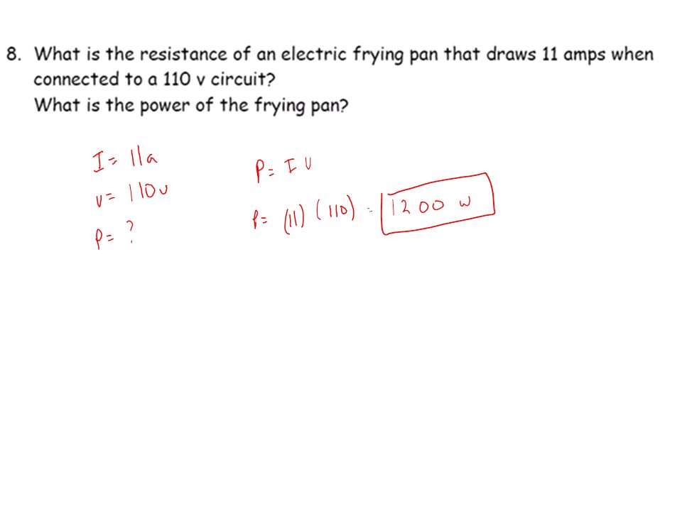
Problem Set 1 What is the resistance of an electric frying pan that draws 12 amps of current when connected to a 110v circuit?

22
Problem Set 1 2. How much current is drawn by a 23Ω lamp when a voltage of 12v is applied?

23
Problem Set 1 3. What is the voltage of a battery if it produces a current of 0.75 amps in a 12Ω resistor?

24
Effects of current on the body
0.001a (1 ma) – barely felt 0.005a (5 ma) – painful 0.010a (10 ma) – muscles contract 0.015a (15 ma) – loss of muscle control 0.100a (100 ma) – can be fatal if the current goes through the heart
 – barely felt a (5 ma) – painful a (10 ma) – muscles contract a (15 ma) – loss of muscle control a (100 ma) – can be fatal if the current goes through the heart.")
25
Safety Notes Electricians often put their hand in their pocket to avoid current going through heart (just in case) Electricians touch a wire they think is not live with the back of their hand so they are not stuck clinching the wire if they were mistakenly wrong

26
Problem set 2 For each problem, calculate the current running through the body and describe its effect: Your hands are wet (R= 2400Ω) and you touch the terminals of a 12v battery. R = 7000Ω and a paper clip is inserted into an 110v electrical socket. 3. A 9.0v portable CD player falls into a hot tub where your R = 100Ω
 and you touch the terminals of a 12v battery. R = 7000Ω and a paper clip is inserted into an 110v electrical socket. 3. A 9.0v portable CD player falls into a hot tub where your R = 100Ω.")
27
Problem Set 2 Your hands are wet (R= 2400Ω) and you touch the terminals of a 12v battery.
 and you touch the terminals of a 12v battery.")
28
Problem Set 2 2. R = 7000Ω and a paper clip is inserted into an 110v electrical socket.

29
Problem Set 2 3. A 9.0v portable CD player falls into a hot tub where your R = 100Ω

30
Problem Set 3 If your pet Peety the parakeet perches on an electric wire. 1. Why isn’t the bird electrocuted? 2. If you fell from a tree onto the same wire, would you be electrocuted? 3. Should you reach up and touch the bird to rescue him?

31
Problem Set 3 If your pet Peety the parakeet perches on an electric wire. 1. Why isn’t the bird electrocuted? No potential difference between feet = no current 2. If you fell from a tree onto the same wire, would you be electrocuted? No potential difference between hands = no current 3. Should you reach up and touch the bird to rescue him? No, you would be the path from the bird to the ground and both of you would be toast. There would be potential difference in this case.

32
Electric Power- Rate of converting electric energy into other energy forms P = W power = work t time The unit for power is the watt 1w = 1J/s Another power equation P=IV

33
Problem Set 4 An appliance draws 13 A when connected to a 110 v circuit. a) What is the power of the appliance b) What is its resistance 2. What is the power of a light bulb that has a resistance of 190 ohms in a 120 v circuit?
 What is its resistance. 2. What is the power of a light bulb that has a resistance of 190 ohms in a 120 v circuit")
34
Problem Set 4 An appliance draws 13a when connected to a 110 v circuit. a) what is the power of the appliance b) What is its resistance
 What is its resistance.")
35
Problem Set 4 2. What is the power of a light bulb that has a resistance of 190 ohms in a 120 v circuit?

36
“Power” companies sell us energy
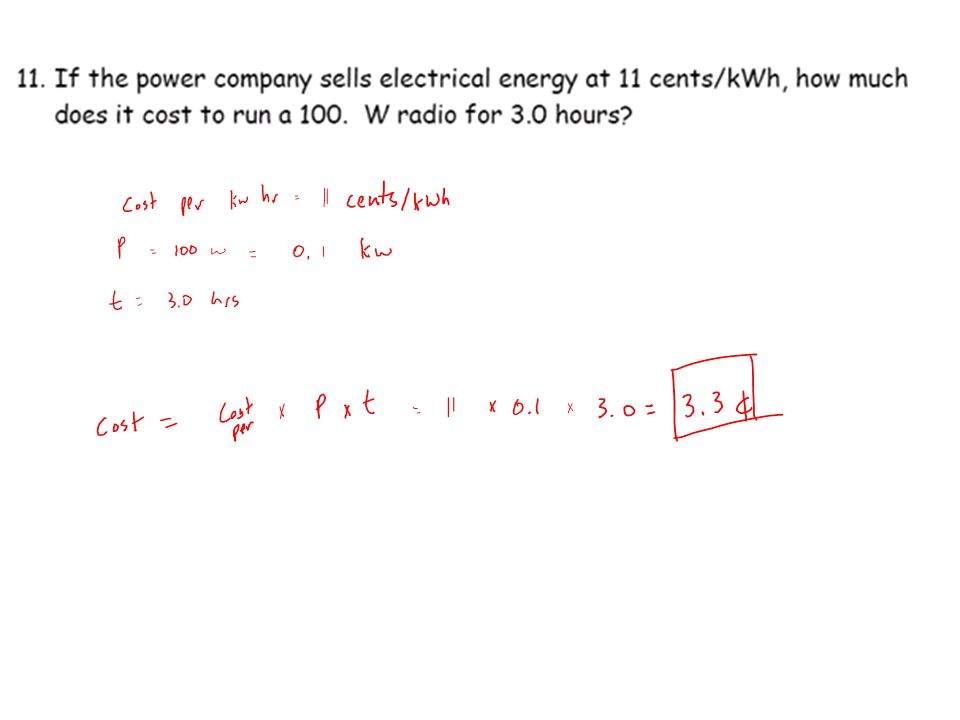
“Power” companies sell us energy. The unit they use for energy is the kilowatt hour. Physics challenge: What is the smallest denomination coin you could use to pay for the energy used by a 60w bulb burning for 8 hours? (at a cost cents per kilowatt hour)
")
37
“Power” companies sell us energy
“Power” companies sell us energy. The unit they use for energy is the kilowatt hour. Physics challenge: What is the smallest denomination coin you could use to pay for the energy used by a 60w bulb burning for 8 hours? (at a cost cents per kilowatt hour)
")
42
The multimeter Used to measure current, voltage, resistance, etc.
The black lead is plugged into the common port The red lead is switched depending on what you are trying to record

43
Measuring Voltage Set up the multimeter to detect voltage.
The black cord should be connected in the middle slot of the multimeter (this will stay here for all readings) The red cord will be placed in the slot to the right of the black that has V or Voltage as one of its symbols Turn the knob to read Voltage for a direct current. Look for V and the symbol for direct current (The symbol for direct current is like an equal sign with the bottom line dashed) _______ _ _ _ _ The voltmeter should be placed outside the circuit
 The red cord will be placed in the slot to the right of the black that has V or Voltage as one of its symbols. Turn the knob to read Voltage for a direct current. Look for V and the symbol for direct current (The symbol for direct current is like an equal sign with the bottom line dashed) _______. _ _ _ _. The voltmeter should be placed outside the circuit.")
44
Measuring Voltage You are measuring the potential difference from one side of the resistor to the other The volt meter should not be part of the circuit Touch each probe to opposite sides of the resistor

45
Set up the multimeter to detect current
The black cord should be connected in the middle slot of the multimeter (this will stay here for all readings) The red cord will be placed in the slot to the left of the black that has A for a reading of Amperes. Turn the knob to read Amperes for a direct current. Look for A and the symbol for direct current.
 The red cord will be placed in the slot to the left of the black that has A for a reading of Amperes. Turn the knob to read Amperes for a direct current. Look for A and the symbol for direct current.")
46
To read current The current must flow through the multimeter and it should be part of the circuit Make it part of the circuit so that electrons must flow through it. Open the circuit and attach one probe to each open end This will once again make it a closed circuit with the multimeter acting as an ammeter in series.

47
Direct Current (dc) Electrons move in one direction
Electrons follow a gradient to where there are less electrons (but we don’t draw it this way)
")
48
Alternating Current (ac)
Electrons change direction In USA, direction changes 60 times per second

49
Conventional way to draw current
Show current moving from the negative to positive Load Battery Closed Switch

50
Series circuits Series circuit:
Resistors are connected in a single path Current must go through every resistor in order Circuit diagram:

51
In a series circuit: Current – stays the same in all parts of the circuit Equation: IT = I1 = I2 = I3 = … Voltage – drops across resistors but adds up to total voltage provided by the battery. (energy is conserved) Equation: VT = V1 + V2 + V3 + … Resistance – Total resistance is found by adding all the resistors Equation: RT = R1 + R2 + R3 + …
 Equation: VT = V1 + V2 + V3 + … Resistance – Total resistance is found by adding all the resistors. Equation: RT = R1 + R2 + R3 + …")
52
Current Explanation IT =3A
Think of three fuel tankers going to fuel stations along a single path. There is only one way to travel so they must all travel past each gas station (resistor) T stands for total 1 for first 2 for second 3 for third I1 = 3A 1 I2 = 3A IT =3A Equation: IT = I1 = I2 = I3 = … 2 I3 = 3A T 3 IT, total current that you start with must go to every resistor
 T stands for total. 1 for first. 2 for second. 3 for third. I1 = 3A. 1. I2 = 3A. IT =3A. Equation: IT = I1 = I2 = I3 = … 2. I3 = 3A. T. 3. IT, total current that you start with must go to every resistor.")
53
Voltage Explanation V1 VT V2 V3
Voltage: every time a new station is visited, some energy is lost. Hence voltage drops. All the voltage is lost at the end, so total voltage is the sum of its parts A fuel pump is needed for a recharge 1 V1 VT Equation: VT = V1 + V2 + V3 + … 2 V2 V3 3

54
Resistance Explanation
Resistance: The more resistors the more total resistance since all the current must pass all the resistors. R1 1 Equation: RT = R1 + R2 + R3 + … RT 2 R2 3 R3

55
Ohms law (V=IR) can be used to calculate an unknown
1 V2=I2R2 VT=ITRT 2 R2 3 V3=I3R3

56
Use the facts about circuits to discover givens in other parts of the circuit so you can solve for variables there. V1=I1R1 1 V2=I2R2 Equation: IT = I1 = I2 = I3 = … Equation: VT = V1 + V2 + V3 + … Equation: RT = R1 + R2 + R3 + … VT=ITRT 2 R2 3 V3=I3R3

57
When you start a circuit problem:
Include all of the missing parts to ohms law V1 = I1 = V2 = I2 = VT = IT = RT = V3 = I3 =

58
Example Problem If you find current anywhere you know it’s the same everywhere. You don’t have enough information off the bat but can figure out RT and use that to solve for current

59
Example Problem If you find current anywhere you know it’s the same everywhere. You don’t have enough information off the bat but can figure out RT and use that to solve for current

60
Example Problem Next use VT and RT to solve for IT which is the same throughout the circuit

61
Example Problem Now we can solve individually for everything

62
Example Problem Now we can solve individually for everything

64
Example Problem

65
Example Problem

66
Example Problem

67
Example Problem

68
Example Problem

69
Example Problem

70
Parallel Circuits Resisters are connected in separate branches
There is more than one path for current

71
Parallel Circuits Resisters are connected in separate branches
There is more than one path for current

72
Parallel Circuits Resisters are connected in separate branches
There is more than one path for current

73
Parallel Circuit Rules:

74
Why resistors in parallel have less resistance than the least one.
Think of resistors as a speed bump that slows down traffic.

75
Why resistors in parallel have less resistance than the least one.
Think of resistors as a speed bump that slows down traffic. 1 resistor slows down the flow or current

76
Why resistors in parallel have less resistance than the least one.
Think of resistors as a speed bump that slows down traffic. 2 resistors in series slows down the flow even more since all cars must go over 2 speed bumps.

77
Why resistors in parallel have less resistance than the least one.
Adding another resistor in parallel also adds another lane. The additional lane speeds up traffic and has a greater effect than the resistor added.

78
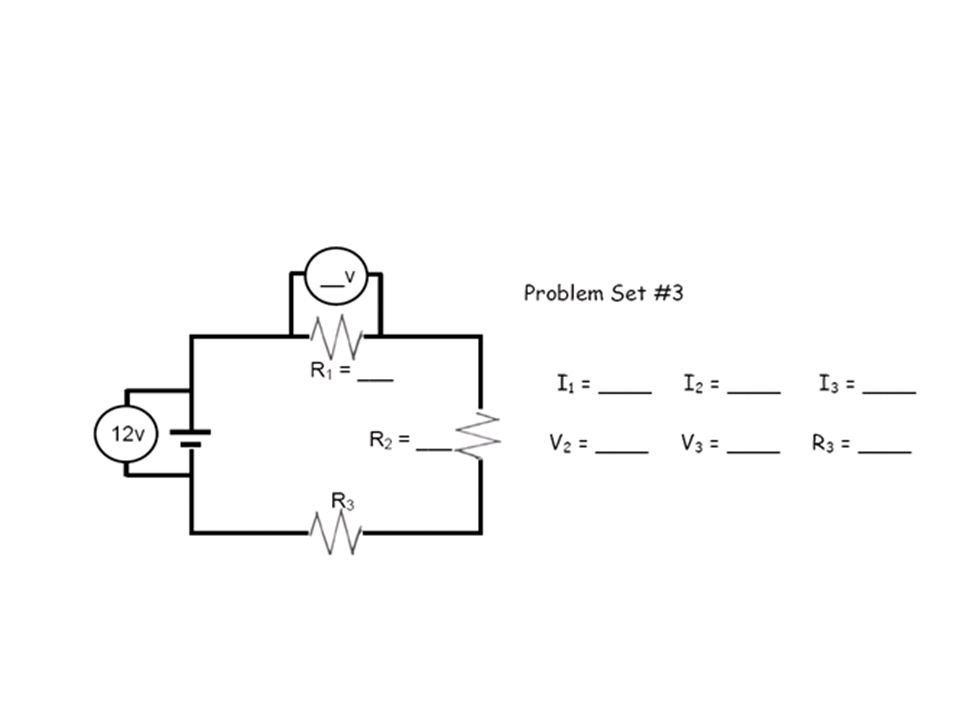
Problem Set #5

83
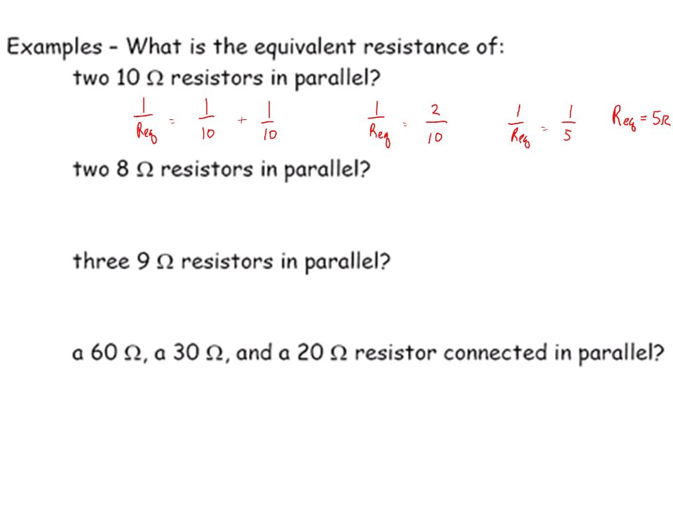
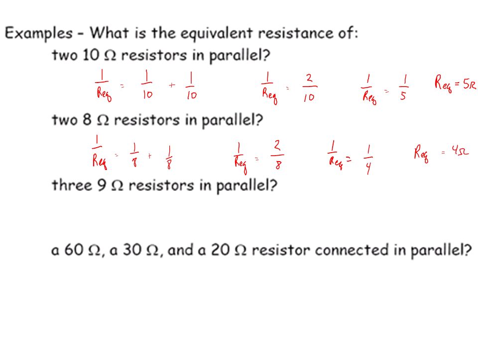
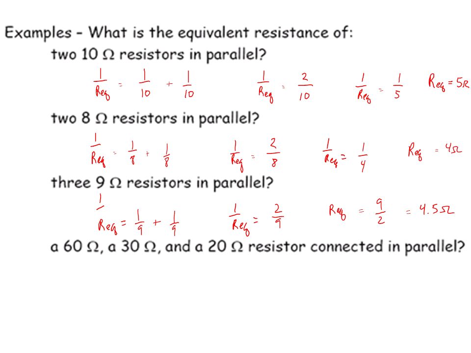
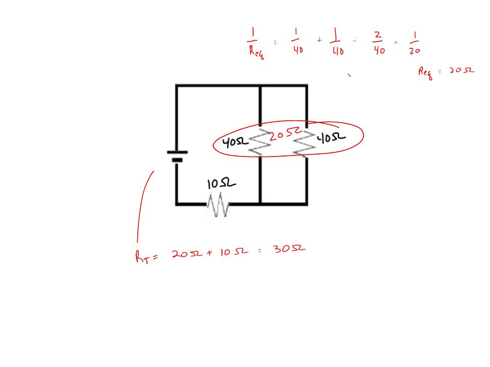
Problem Set #5 Find the resistance of the following resistors in parallel 1. 12 ohms, 12 ohms, 12 ohms 2. 36 ohms, 12 ohms, 9 ohms, 36 ohms 3. 60 ohms, 60 ohms, 30 ohms

84
Problem Set #5 Find the resistance of the following resistors in parallel 1. 12 ohms, 12 ohms, 12 ohms 2. 36 ohms, 12 ohms, 9 ohms, 36 ohms 3. 60 ohms, 60 ohms, 30 ohms

85
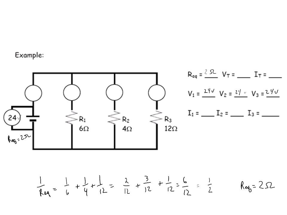
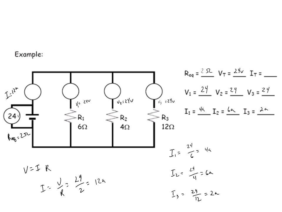
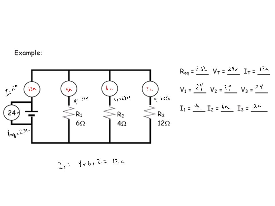
Problem Set #6 24V

86
24V

90
R2 12V 12 6

91
R2 12V 12 6

92
R2 12V 12 6

93
R2 12V 12 6

94
3a 30V 30

95
3a 30V 30

96
3a 30V 30

97
3a 30V 30

98
Complex Circuits Are a mixture of parallel and series circuits
Suggestion: Work your way to one big series circuit where all the resistors are in series. If the current has to go through the resistor and has no other option, it is in series.

99
Problem Set #7 Determine which of the following are in series, parallel, or both. A. Series B. Parallel C. Parallel D. Series E. Series F. Series G. Series w/ H & parallel H. Series w/ G & parallel I. Parallel

100
Start by finding the resistors connected in parallel
B-CEq Start by finding the resistors connected in parallel B and C are in parallel The equivalent of B and C act like it is in parallel with A and D

101
Suggestion: Work your way to one big series circuit where all the resistors are in series.
If the current has to go through the resistor and has no other option in order to get back to the power source, it is in series.

102
Try this one

103
G and H are in series The combo of series G-H and I are in parallel That whole combo of G-H series in parallel with I act as a single resistor in series with F and E

104
Try this one

105
Complex Circuit (Example G)
Try This

106
Complex circuit

107
Complex circuit

108
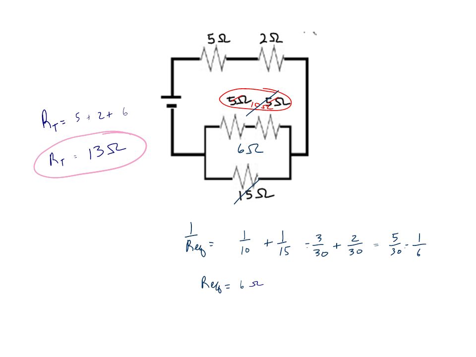
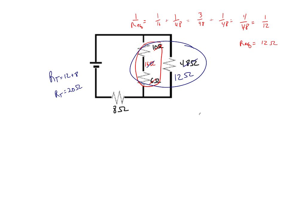
Complex circuit

109
Complex circuit Like a 2 ohm Resistor in series

110
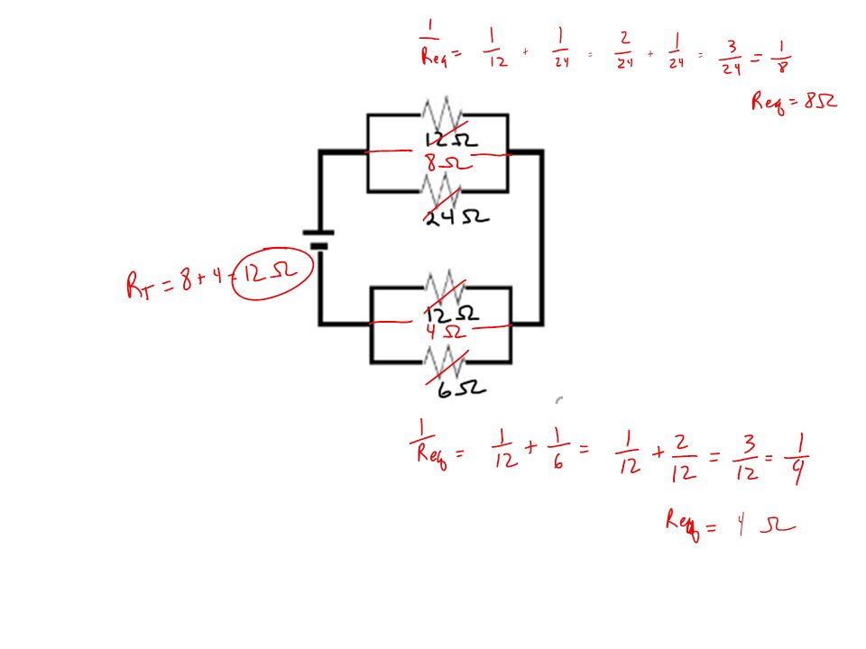
Problem Set #8 (Find the RT for each)
")
115
Solving complex circuit problems Example H:
Start by seeing if you are given all the values of the resistors If you are calculate the total resistance

116
Solving complex circuit problems Example H:

117
Solving complex circuit problems Example H:
Now we have 2 of three totals and can do ohms law

118
Solving complex circuit problems Example H:
I1 is in series and therefore all the current from the battery flows here.

119
Solving complex circuit problems Example H:
V1 and V2 both have the same voltage since they are in series. 30 V are left over since RT = 40V and I1 = 10V

120
Solving complex circuit problems Example H:

121
Problem Set #9 (1) 30V 24 12 2
 30V")
122
Problem Set #9 (1) 30V 24 12 2
 30V")
123
Problem Set #9 (1) 30V 24 12 2
 30V")
124
Problem Set #9 (1) 30V 24 12 2
 30V")
125
Problem Set #9 (1) 30V 24 12 2
 30V")
126
Problem Set #9 (1) 30V 24 12 2
 30V")
127
Problem Set #9 (2) 12v 12 12 6a
 12v a")
128
12v 12 12 6a

129
12v 12 12 6a

130
12v 12 12 6a

131
Problem Set #9 (3) 30V 24V 6 12
 30V 24V 6 12")
132
30V 24V 6 12

133
I can do this with Physics!!
Honors Book Fun!! I can do this with Physics!!

134
#39 Three resisters, 25, 45, and 75 ohms are connected in series and a 0.51-A current passes through them. What is (a) the total resistance (b) the potential difference across the resistors?
 the total resistance (b) the potential difference across the resistors")
135
#39 Three resisters, 25, 45, and 75 ohms are connected in series and a 0.51-A current passes through them. What is (a) the total resistance (b) the potential difference across the resistors?
 the total resistance (b) the potential difference across the resistors")
136
#43

137
#43

138
#54

139
#54

140
#59

141
#59

142
#60

143
#60

144
#61

145
#61

146
Notes on short circuits
Can be caused by an overload Usually occurs when wires become fray and touch one another The current bypasses the devices plugged in and there is a large decrease in resistance. The current increases as a result causing the wire to heat up

147
Two main short circuit dangers
Electric shock Fire – the byproduct of current is heat

148
Safety devices to stop a short circuit
Fuses- a short thin piece of metal wired into a circuit that will melt at a certain temperature caused by a certain current. (must be replaced when they blow) Circuit breakers- composed of a bimetallic strip. One metal expands faster than the other causing it to curl. The curling causes a break in contact that opens the circuit. The circuit would have to be reset to be closed again.
 Circuit breakers- composed of a bimetallic strip. One metal expands faster than the other causing it to curl. The curling causes a break in contact that opens the circuit. The circuit would have to be reset to be closed again.")
149
How a circuit breaker works

150
Problem set #6 An ammeter is connected in __________ because current ___________________ 2. An ammeter has ________ resistance so that it will not greatly alter the current in the circuit.

151
Problem set #6 An ammeter is connected in __________ because current ___________________ 2. An ammeter has ________ resistance so that it will not greatly alter the current in the circuit.

Similar presentations


 Electrons (-) Neutrons (0)>")

 _____ circuit.>")
 Sources: Battery, 120 V plug,>")
 electrons.>")


 Negative More.>")


