Download presentation
Presentation is loading. Please wait.

1
STRUCTURAL ENGINEERING

2
What Does a Structural Engineer Do?

3
What Does a Structural Engineer Do?

4
Phil Druker, UI English Dept. Bridge in Dopal region of Nepal. 2005.

7
Roles of a Structural Engineer
Lead engineer/Project engineer Consultant for an architect Consultant for another engineer, insurance companies, lawyers, etc. As well as: Aerospace design. Product design, etc. for industries. Facilities engineer.

8
Lead or Project Engineer
Defines project goals Costs Performance requirements Supervises design based on these requirements. Outlines tasks What needs to be done & who will do it Organizes Project Calendar Sequence

9
Palm Valley Interchange
Rich: Thought you might like this - recent air photo of the post-tensioned ps girder bridge I mentioned in my previous note. Not much in the photo for scale. The main span is 290 feet flanked by 210-foot side spans. Haunched girders are 140 feet in length; haunches vary in depth from 8 to 15 feet at the river pier bearings. Each girder of the 710-foot three span continuous main span portion of the structure is post-tensioned with four tendons comprised of " dia 270 ksi strand. Approaches utilize standard 72" Florida Bulb-T's and are comprised of six 119-foot simple spans typical each side. - Jim Aronson

10
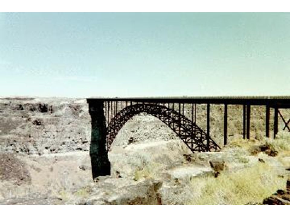
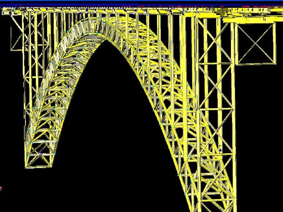
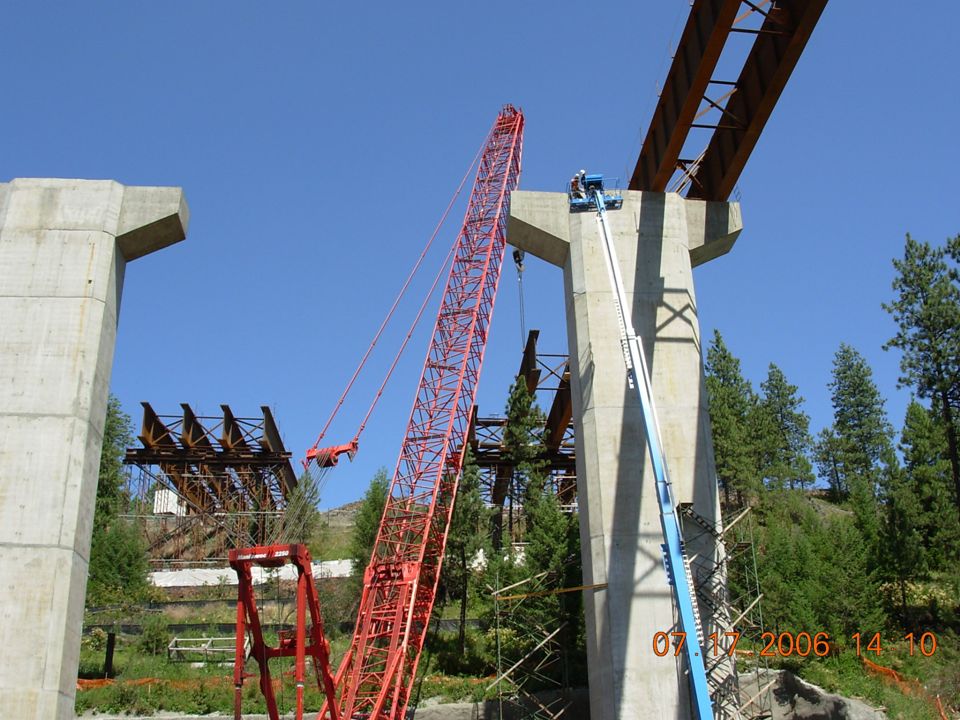
Chris Boyd, HDR, Lake Creek Bridge, south of Coeur d’Alene, Idaho

12
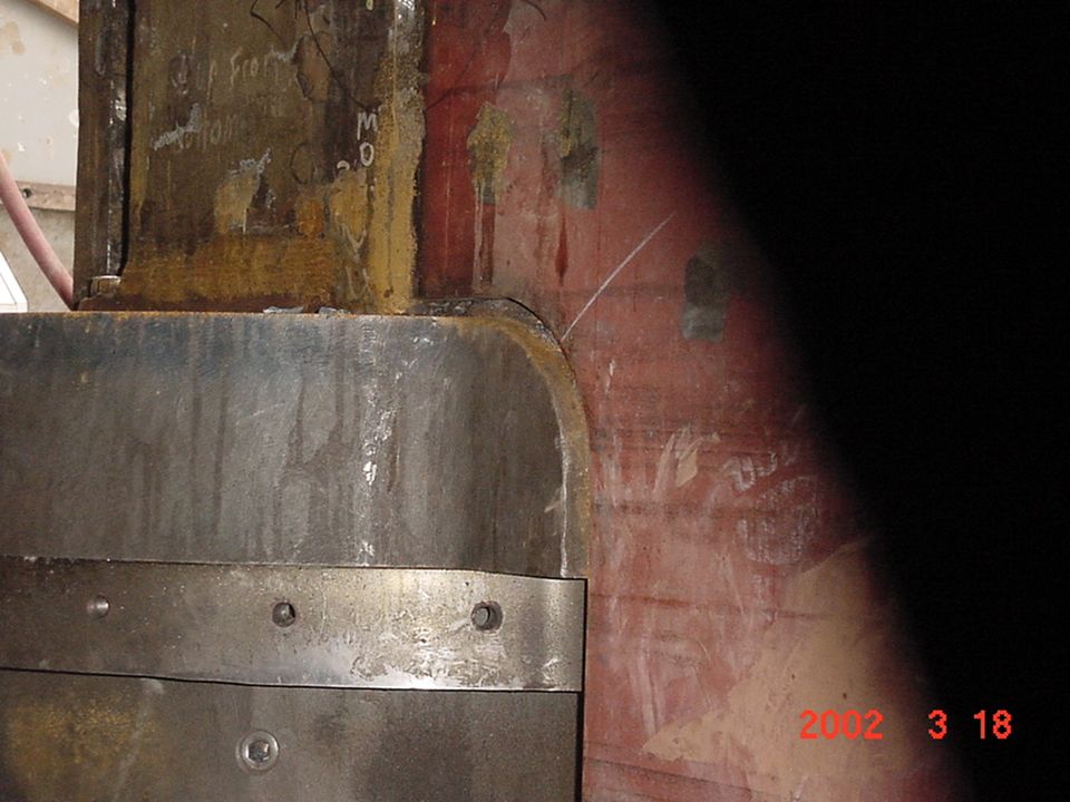
Lower Granite Dam Lock Repair – Jarrod Milligan
Jarrod Milligan, Corps of Engineers

14
Consulting for an Architect or Engineer
The architect works with the client to establish project requirements: space requirements and relationships siting aesthetics lighting budget

15
Consulting for an Architect or Engineer
The engineer’s job is to make the architect look good. Ensure integrity of structure Provide economical solutions. Develop innovative ways to solve new problems and use new materials.

16
Boise Air Terminal Boise Air Terminal: Brian Sielaff – Formerly from CSHQA, Boise

17
Riley Mahaffey, Jess Haldeman, Ted Eggerton, Lochsa Engineering: Wynn Hotel, Las Vegas

18
Mandalay Bay Hotel, also by Lochsa

19
Forensic Engineering Finding out what went wrong. Insurance companies
Lawyers

20
Forensic Engineering: Damage to offshore oil rig, Hurricane Katrina, 2005 – Anthony Mannering

21
Hall Street overpass I-70, Hays Kansas, Feb. 14 2006, Ted Bush HDR:
> It will be days or even weeks before a bridge is repaired over > Interstate Highway 70 that was nearly ripped in half Monday when it was > struck by a backhoe boom being carried on a flatbed truck. > > A bridge evaluation crew from Topeka was on its way to Hays this morning > to examine the damage, said Kevin Zimmer, Hays, an engineer with the > Kansas Department of Transportation. > > The backhoe, which runs on tracks, was still stuck in the bridge Tuesday > morning, he said. Eastbound lanes are closed for two miles. > > The truck driver, Michael M. Conley, 53, Holcomb, had driven onto the > Interstate one mile west of the bridge, Zimmer said. The boom of the > backhoe was about three feet too high for the bridge that crosses Hall > Street at Hays. > > When the bridge was struck at 5:53 p.m. Monday, the boom extended and > ripped through the concrete bridge deck, Zimmer said. > > No one was injured.

23
Design Loads Design loads include: Dead loads Live loads
Self-weight, “Permanent” contents. Live loads Occupants, Transient contents Environmental loads Wind, snow, earthquake, etc.

24
Uncertainty Dead loads can be predicted with some confidence.
Live load and environmental load predictions are much more uncertain. E.g., it is nearly impossible to say what will be the exact maximum occupancy live load in, say, a classroom. It is also difficult to say how that load will be distributed in the room.

25
Lochsa Engineering: Grand Canyon Skywalk, beyond scope of code-specified wind loads. On-site wind load data was collected.

26
Weather station including horizontal anemometer on tower just outside the boundary fence. Anemometer for vertical wind data collection located in silver tube on cliff face. See also:

27
Under Construction 2006; due to open March 2007.

28
Uncertainty (cont.) Structural codes account for this uncertainty two ways: We chose a conservative estimate (LARGE estimate) for the load: E.g., a “50-year” wind load, which is a wind load that occurs, on average, only once in 50 years. We factor that estimate upwards just to be sure.

29
Load Factors Newer codes have separate load and resistance factors:
Load factors “overestimate” the load. Resistance factors “underestimate” the strength of the structure. Dead load factors range from 1.1 to 1.4 Smaller uncertainty. Environmental and live load factors range from 1.7 to 2.0 and higher. Higher uncertainty

30
Simplified Wind Loads Since we can’t predict exactly the maximum load a given structure will experience, the code provides: Rational procedures for estimating a reasonable maximum value Procedures for arranging the loads on the structure. Experience has shown that if the engineer follows these procedures he/she can expect the structure to perform properly (i.e., not collapse, etc.)
")
31
Wind Loads What factors should the wind design loads consider?

32
Summary Design loads used by engineers represent rational estimates of loads that we should consider in our design. Experience has shown if we design for these loads, the building should survive for a reasonable amount of time (50 years or more).
.")
33
Summary (cont.) The models try to consider situations that will have a significant effect on the design load. Max wind speed, building height and shape, etc. The maximum loads estimated by the design codes are then factored to add a safety margin to our calculations.

34
Example Building

35
Design Methods Method 1 – Simplified Procedure:
Simple diaphragm building, Low-rise, Enclosed, Regular geometry, symmetric, Not flexible, prone to flutter/vortex shedding, torsion etc. Method 2 – Analytic Procedure. Method 3 – Wind Tunnel Procedure.

36
Wind Loads on Structures

37
Gust Factor, G G = 0.85 for rigid, low rise buildings

38
Wall Pressure Coefficients, Cp

39
Wind Velocity Pressure

40
Importance Factor Agriculture Buildings Category I
“Typical” Buildings Category II Hazardous Buildings Category III Essential Facilities Category IV

41
Wind Load Map: Western US
Wind speeds in MPH (kph)
")
42
Velocity Pressure Exposure Coefficients
Exposure B, Case 2

43
Velocity Pressure Exposure Coefficients Notes
Case 1 a. All components and cladding. b. Main wind force resisting system in low-rise structure designed using Figure 6-10 [Method 2]. Case 2 a. All main force wind resisting systems in buildings except those in low-rise buildings designed using Figure 6-10. b. All main wind force resisting systems in other structures. We will use Case 2.

44
Velocity Pressure Exposure Coefficients (cont.)
")
45
Exposure Categories Exposure B: Exposure C Exposure D
Urban and suburban areas, wooded areas… Exposure B shall be assumed unless the site meets the definition of another type of exposure. Exposure C Open terrain with scattered obstructions… Exposure D Flat unobstructed areas exposed to wind flowing over open water for a distance of at least one mile…

46
Directionality Factor Kd

47
Topographic Factor Kzt
If flat terrain Kzt = 1

48
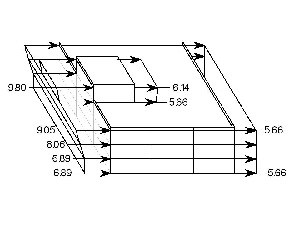
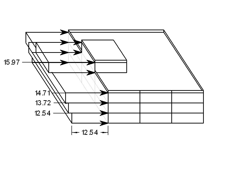
Wind Loads Calculate Wind Loads Wind From East Wind From West

Similar presentations


 of representative samples or strength parameters or slope.>")


