Download presentation
Presentation is loading. Please wait.

1
Ponds 6, 7 & 8 Design Update Napa Sonoma Marsh Restoration Group Meeting USGS San Pablo Field Station Office, Building 505, Mare Island April 17, 2008

2
Presentation Schedule Project Design Overview Mixing Chamber Design Water Quality Sampling

3
50% Design Submitted April 2007 90% Design Submitted February 2008 Waiting on USACE Input for Design Permitting Ongoing Schedule

4
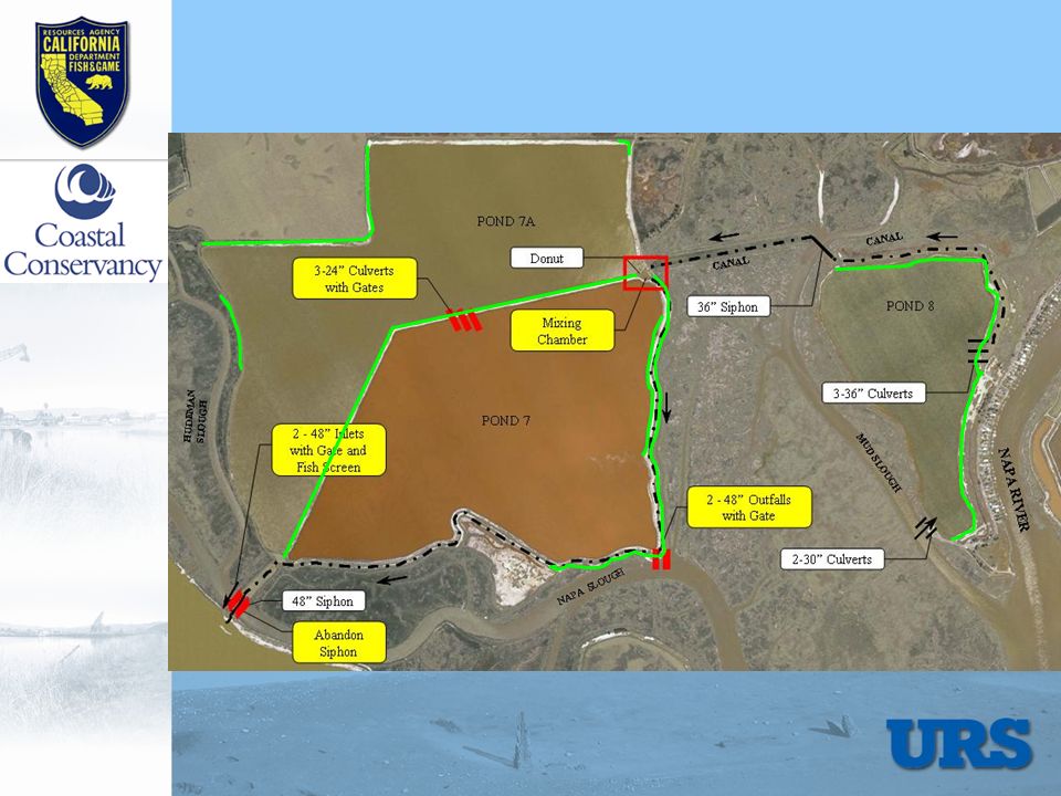
Location Map

5
Ponds 6/6A Project Objectives Maximize Habitat for Shorebirds and Waterfowl Improve Management Flexibility Improve Levees

6
6A Donut 6 Donut POND 6A POND 6 CANAL NAPA SLOUGH CHINA SLOUGH DEVIL’S SLOUGH NAPA SLOUGH Abandon Siphon 48”Inlet/Outlet with Gate 2-36” Inlet/Outlet with Gates 4-36” Outfalls with Gates LITTLE ISLAND FARM 4 - 36” Inlet/Outlet with Gates 48” Siphon 4 - 36” Culverts with Gates 2 - 36” Inlet/Outlet with Gates 48” Siphon

7
Upper Ponds Project Objectives Pond 7 Bittern Reduction in 8 years New Outfall to Napa Slough Demolish Siphon to Ponds 6/6A Improved Pond Management Flexibility

11
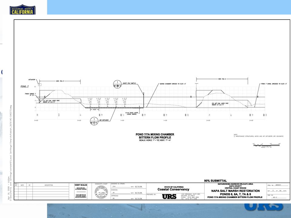
Mixing Chamber - General Setting Design Criteria for the Mixing Chamber are: Mixing chamber inflow of ambient ~ 14,000 afy Initial bittern release = 1% of Mixing chamber inflow = 140 afy Design to provide flexibility for future increase in bittern release Provide complete mixing

12
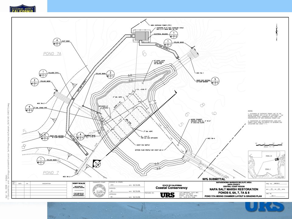
General Setting Pond 7A Pond 8 Pond 7 (Bittern) Mixing Chamber
 Mixing Chamber")
13
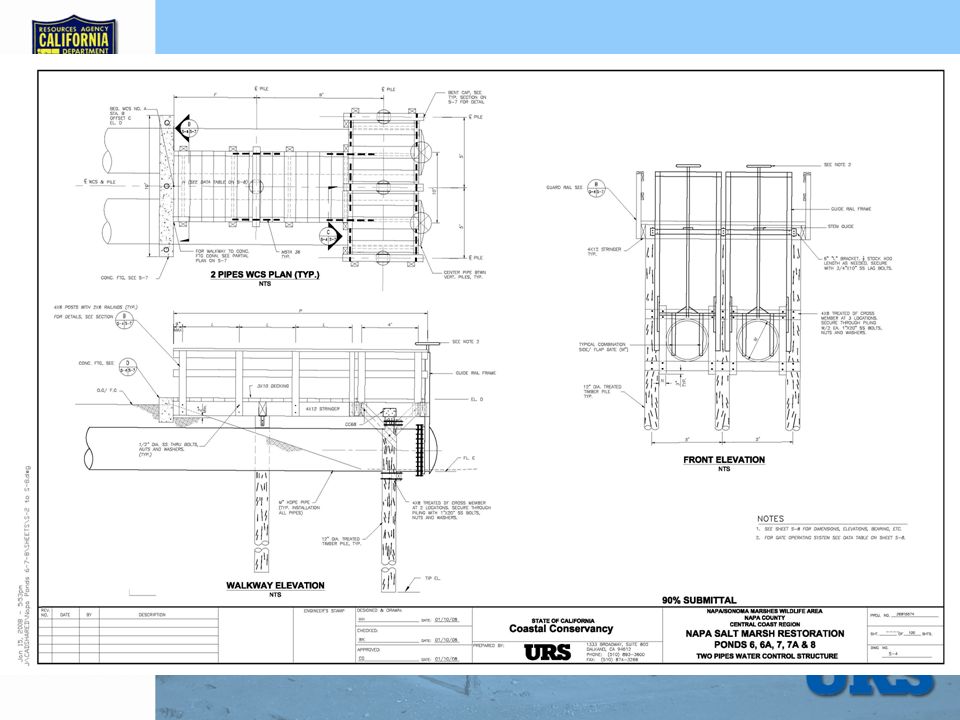
CANAL FROM POND 8 INTERNAL LEVEE POND 7 POND 7A 36” WIDE SLUICE GATE POND 7/7A DONUT (MIXING CHAMBER) NEW CONTROL STRUCTURE INVERT AT 2.5 FT NEW 36” INLET WITH GATE INVERT AT 2.5 FT 2 NEW 36” CULVERTS WITH GATES INVERT AT 2.5 FT 2 NEW 48” OUTFALL WITH GATE INVERT AT 0 FT Design Schematic DREDGE CANAL TO EL. 0 FT 2 NEW 48” OUTFALL WITH GATES INVERT AT 0 FT DREDGE MIXING CHAMBER TO EL. 0 FT

14
Automated System Automated System was Selected: Highest Flexibility – given design uncertainties, provides flexibility for post-construction calibration and adjustments to meet field conditions Data collection & reporting capabilities Emergency notifications Standard gates available for future habitat pond management Less long-term infrastructure to demo

15
Level Sensor Flow Sensor Gate Actuator Water Quality DB Cables Control System Concept Mixing Chamber Terminal Building Power Communications Pond 7 Pond 7 Channel Pond 8 Channel Pond 7A

16
Mixing Power Requirement Elevation, z [m] Density, [kg/m 3 ] zmzm z0z0 zbzb ambient 1,010.6 fully-mixed 1,023.6 bittern 1,256.9 Fully-mixed density profile Stratified density profile Mixing chamber bathymetry Thickness of bittern layer The energy required to mix the water column completely depends on: Bittern and ambient water density difference Water depth in the Mixing Chamber
![Mixing Power Requirement Elevation, z [m] Density, [kg/m 3 ] zmzm z0z0 zbzb ambient 1,010.6 fully-mixed 1,023.6 bittern 1,256.9 Fully-mixed density profile Stratified density profile Mixing chamber bathymetry Thickness of bittern layer The energy required to mix the water column completely depends on: Bittern and ambient water density difference Water depth in the Mixing Chamber](http://images.slideplayer.com/25/7854105/slides/slide_16.jpg "Mixing Power Requirement Elevation, z [m] Density, [kg/m 3 ] zmzm z0z0 zbzb ambient 1,010.6 fully-mixed 1,023.6 bittern 1,256.9 Fully-mixed density profile Stratified density profile Mixing chamber bathymetry Thickness of bittern layer The energy required to mix the water column completely depends on: Bittern and ambient water density difference Water depth in the Mixing Chamber")
17
Mixing Power Available Available Power Power Required

20
Ponds 7, 7A, and 8: Water Quality Sampling 4 Monitoring Locations Pollutants/Parameters Pesticides/PCBs, volatile organics, semi-volatile organics, metals, mercury, chromium VI, hardness, turbidity Field Measurements Dissolved oxygen, pH, salinity, water temperature, tidal stage, weather Sampling Schedule Two sampling events: Spring and Fall 2008

21
Ponds 7, 7A, and 8: Monitoring Locations

22
Questions?

23
Terminal Building System Components in the Terminal Building Controller (PLC) – Gate control Remote Terminal Unit (RTU) – Data collection Batteries/Charger – Provides Power Radio/ Antenna – Offsite Data Communications Gate Control Master Panel – Local manual gate control Intrusion Sensors (Door Switch/Motion Sensors)
 – Gate control Remote Terminal Unit (RTU) – Data collection Batteries/Charger – Provides Power Radio/ Antenna – Offsite Data Communications Gate Control Master Panel – Local manual gate control Intrusion Sensors (Door Switch/Motion Sensors)")
24
The hydraulic problem is… Pond 7 WSEL does not allow for continuous gravity flow into MC Pond 7A, Pond 8, and Mixing Chamber Pond 7 (Bittern)
")
25
The solution to the hydraulic issue Issue: Pond 7 WSEL Does Not Allow for Continuous Bittern Gravity Flow into MC Increase WSEL Lower WSEL Maintain Dilution Ratio

26
Maximum Allowable Water Surface Elevations in Pond 7 Top of Levee (7 – 9 ft NAVD88) Wave runup (0.2 - 0.8 ft) Emergency (0.5 ft) Storage WSEL (4.7 ft NAVD88) LEVEE Freeboard (1 ft) Recommendations Target WSEL in P7 is 4.7 feet Target WSEL in the Mixing Chamber < 4.7 feet Pond Bottom (2-3 ft NAVD88)
 Wave runup ( ft) Emergency (0.5 ft) Storage WSEL (4.7 ft NAVD88) LEVEE Freeboard (1 ft) Recommendations Target WSEL in P7 is 4.7 feet Target WSEL in the Mixing Chamber < 4.7 feet Pond Bottom (2-3 ft NAVD88)")
27
Hydraulic simulation results MIKE 11 model run Alt02_Iter09.res11 Pond 7A Pond 7 Pond 8 Mixing Chamber Napa Slough

Similar presentations


. Elevations are in feet, NGVD29.Form USGS data;>")


