Download presentation
Presentation is loading. Please wait.

1
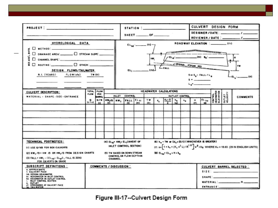
CTC 261 Hydraulics Culvert Design Form

2
Objectives Know how to use the culvert design form to evaluate and size simple culverts

3
Definitions HWo=Headwater depth above outlet invert

4
Step 1 Summarize all known data and select a preliminary culvert size, shape and entrance type

5
Step 2-Inlet Control Calculations
Determine HW/D from Design Charts Calc HW depth Calc Fall Calc the Elev of the HW for inlet control

6
Step 3-Outlet Control Calculations
Determine TW depth Determine critical depth Find the average of critical depth and diameter Determine depth from culvert outlet invert to HGL Determine all head losses Calc the Elev of the HW for outlet control

7
Step 4-Evaluate Results
Higher of the two elevations designates control Choose larger culvert if the highest elevation is unacceptable

9
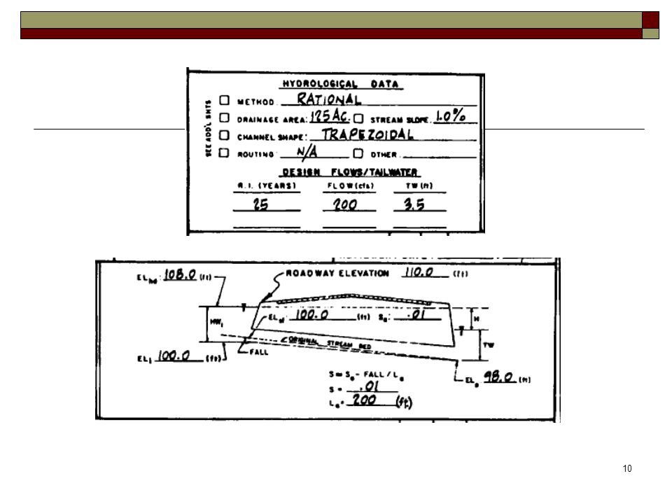
Example Problem 1 Q25=200 cfs Natural channel slope=1% TW=3.5 ft
L=200 ft Natl streambed entrance = 100 ft Shoulder Elev=110 ft (2-ft freeboard) Evaluate 72” (6’) CMP (45 deg bevel)
 Evaluate 72 (6’) CMP (45 deg bevel)")
11
Step 2 Inlet Control Calculations
HW/D from Design Chart 3B = 0.96 HW=0.96*6’=5.8’ A =45 deg bevel, pg 27 B =33.7 deg bevel

12
Step 2-Inlet Control Calculations Calculate Fall
Max. Available HW depth = = 8’ Fall = Calc HW depth – Available HW depth 5.8’-8’= -2.8 ft Fall is negative; therefore set fall = 0 Note: If fall is + then the invert must be lowered to allow enough head to “push” desired Q through the culvert

13
Step 2-Inlet Control Calculations Calculate HW Elev for inlet control
ELhi=HWi+ELi 5.8 ft ft = feet

Similar presentations


 Principles of hydraulics 1.Conservation of energy 2.Continuity (conservation of mass)>")


. 2. Waterway-Waterway (syphon or.>")


 Confirm Outlet Drainage Needed Select DC, Spacing.>")

