Download presentation
Presentation is loading. Please wait.

1
ENGR 100 Engine Dissection Project Information

2
Engine Dissection Project 3.5 HP single cylinder, 4 cycle engine, made by Briggs and Stratton in Milwaukee, Wisconsin. Used in lawn mowers, snow blowers, go-carts, etc. (ref. 2, Used by permission of Briggs and Statton, ©1992, all rights reserved)
.")
3
Engine Dissection Project Divide into groups. Start engine. Disassemble engine (follow directions!) Review parts and functions – Ask questions! Reassemble engine (follow directions!). Re-start engine.
 Review parts and functions – Ask questions. Reassemble engine (follow directions!). Re-start engine..")
4
Engine Project Assignments Group Assignment: Engine Questions (HW points) Individual Assignments: Engine Dissection Report explain how the engine works you can choose to explain a different engine (requires instructor’s permission) Engine Team Contribution Survey
 Individual Assignments: Engine Dissection Report explain how the engine works you can choose to explain a different engine (requires instructor’s permission) Engine Team Contribution Survey")
5
Engine background Engine converts gasoline into motion. Internal combustion engine: the gasoline is burned inside an engine External combustion engine: the gasoline is burned outside an engine Example: steam engine – fuel burns outside the engine to create steam, and the steam creates motion inside the engine.

6
Engine basics reciprocating internal combustion engine: small amount of high- energy fuel (like gasoline) in an enclosed space fuel is ignited energy is released in the form of expanding gas this energy is converted into motion
 in an enclosed space fuel is ignited energy is released in the form of expanding gas this energy is converted into motion")
7
Four-stroke combustion cycle a.k.a. Otto cycle (invented by Nikolaus Otto in 1867). Four strokes: intake compression power (combustion) exhaust
 exhaust.")
8
Engine parts

9
Intake Stroke Intake valve opens, admitting fuel and air. Exhaust valve closed.

10
Compression Stroke Both valves are closed. Fuel/air mixture is compressed by rising piston. Spark plug ignites mixture at end of stroke.

11
Combustion Stroke Fuel-air mixture burns, increasing temperature and pressure. Expansion of combustion gases drives piston down. Both valves are closed. Exhaust valve opens at end of stroke.

12
Exhaust Stroke Exhaust valve open. Exhaust products are displaced from cylinder. Intake valve opens at end of stroke. 4-stroke cycle repeats.

13
Intake Stroke Intake valve opens, admitting fuel and air. Exhaust valve closed for most of stroke Compression Stroke Both valves closed, Fuel/air mixture is compressed by rising piston. Spark ignites mixture near end of stroke. Intake Manifold Spark Plug Cylinder Piston Connecting Rod Crank Combustion Stroke Fuel-air mixture burns, increasing temperature and pressure, expansion of combustion gases drives piston down. Both valves closed - exhaust valve opens near end of stroke 1 2 3 4 Exhaust Stroke Exhaust valve open, exhaust products are displaced from cylinder. Intake valve opens near end of stroke. Crankcase Exhaust Manifold Exhaust Valve Intake Valve Four-stroke combustion cycle

14
1. Intake2. Compression 3. Combustion 4. Exhaust

15
Animation of four strokes

16
Engine parts: crankshaft Turns the piston's up and down motion (linear motion) into circular motion. Think of pedaling a bicycle. Image from http://www.eng.iastate.edu/explorer/topics/car/engine.htm

17
Engine parts: crankshaft Image from toyotaperformance.com/crankshaft_kits.htm

18
Engine parts: piston Image from www.eng.iastate.edu/explorer/topics/car/engine.htm Piston rings provide a sliding seal: prevent the fuel/air mixture and exhaust in the combustion chamber from leaking into the sump during compression and combustion. prevent the oil in the sump from leaking into the combustion area (“burning oil”).
..")
19
Engine parts: camshaft Image from http://www.ul.ie/~kirwanp/camshaftanimation.htm Rod with a series of oblong protrusions called lobes. As the camshaft rotates, the lobes push against the valves (usually via an intermediate component known as a tappet or lifter), causing them to open at the appropriate time. The valves are spring- loaded, closing after the protruding camshaft lobe releases the valve.
, causing them to open at the appropriate time. The valves are spring- loaded, closing after the protruding camshaft lobe releases the valve..")
20
Image from http://www.keveney.com/otto.html Overhead camshaft Camshaft is positioned at the top of the cylinder. Camshaft is driven by the crankshaft via gears. Each valve opens only once during the four- stroke cycle; that is, the camshaft makes one rotation for every two rotations of the crankshaft.

21
piston valve rocker valve lifter camshaft cam crankshaft push rod Timing marks Image from Automotive mechanics, 8th ed. By William H. Crouse

22
Lubrication The lubrication system makes sure that every moving part in the engine gets oil so that it can move easily. Oil is pumped under pressure to all the moving parts of the engine by an oil pump. The oil pump is mounted at the bottom of the engine in the oil pan. The oil pump is connected by a gear to either the crankshaft or the camshaft. Image from http://www.innerauto.com/innerauto/anim/engi.html

23
Engine parts: carburetor Fuel Higher Pressure Outside Engine Venturi (creates low pressure) Choke Throttle (controls how much air can flow through the carburetor) Pressing the accelerator causes the throttle to open. Air moves into the carburetor and is restricted by the venturi. Low pressure is created at the restriction. Fuel is drawn into the venturi from the bowl through and is mixed with the air. Air-fuel mixture exits through the intake valves into the cylinder.

24
Fuel injection Forces the fuel through nozzles under pressure, rather than using the force of the air rushing through. Precise control of the amount of fuel mixed with air: increase fuel efficiency, decrease pollution.

25
Fuel injection Monitored Engine Operating Conditions: Manifold Pressure Engine Speed Air Temperature Coolant Temperature Acceleration COMPUTER TRIGGER INJECTOR DRIVE UNIT Pressure Regulator Fuel Filter Fuel Pump FUEL TANK Injectors

26
Typical cylinder arrangements Image from http://www.sigetyracing.com/sigetyracing_008.htm Image from http://www.familycar.com/engine.htm

27
What to do first? Divide into teams. Get each other’s email address. Team work (15 min): talk about your experience with engines (if any), read directions for the engine project and decide who is doing what roles. Get an engine, mount it on an aluminum plate use at least two bolts the starting cord must be over the excess plate surface -- and the shaft should be reaching out over open space.
: talk about your experience with engines (if any), read directions for the engine project and decide who is doing what roles. Get an engine, mount it on an aluminum plate use at least two bolts the starting cord must be over the excess plate surface -- and the shaft should be reaching out over open space..")
28
What to do first (cont.)? Note the manufacturer, model, and serial number of your engine. What is the idle RPM and rated horsepower for this engine?

29
Starting the engine Take the engine to the parking lot outside the main door of the building. Put a small amount of fuel in the gas tank (about 1/4 cup). Put about a 1/2 cup of oil into the oil filler hole. Engage the choke completely and open the throttle all the way (to the "rabbit" position). Two team members must hold the engine steady by standing on each side of the plate.
. Put about a 1/2 cup of oil into the oil filler hole. Engage the choke completely and open the throttle all the way (to the rabbit position). Two team members must hold the engine steady by standing on each side of the plate..")
30
Starting the engine (cont.) Then, a third member pulls the cord to start the engine. Allow the engine to run only a few seconds or it will get too hot to handle! Stop the engine. Drain the fuel back into the red fuel container, then drain the oil into the black oil container. Return the engine to the lab. Begin engine dissection and answering questions

31
How Do Engines Work? How does the engine complete these Primary Functions? Get started? Suck in fuel? Suck in air? Mix air and fuel? Compress the mixture? Ignite the mixture (at the right time)? Make the combusting gases do work? Make the work available to somebody? Exhaust the gases? Shut off?
. Make the combusting gases do work. Make the work available to somebody. Exhaust the gases. Shut off .")
32
How Do Engines Work? How does the engine complete these Secondary Functions? Stay lubricated? Operate the valves at the right time? Smooth out the power pulses? Store the fuel? Keep cool? Make it easy to start?

33
2-Stroke Process Compression (ports closed) Air Taken Into Crankcase Combustion (ports closed) Exhaust (intake port closed) Air compressed in crankcase Scavenging and Intake (ports open)
 Air Taken Into Crankcase Combustion (ports closed) Exhaust (intake port closed) Air compressed in crankcase Scavenging and Intake (ports open)")
34
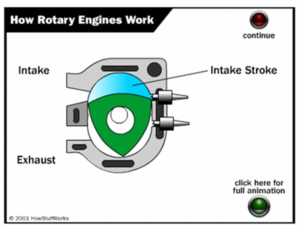
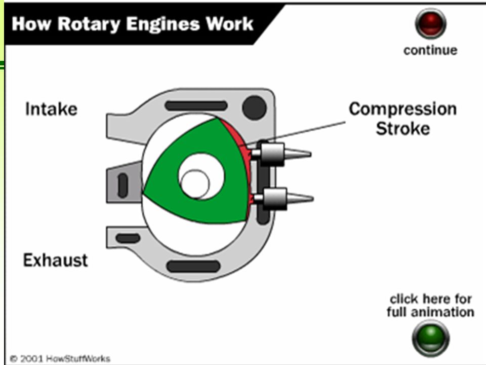
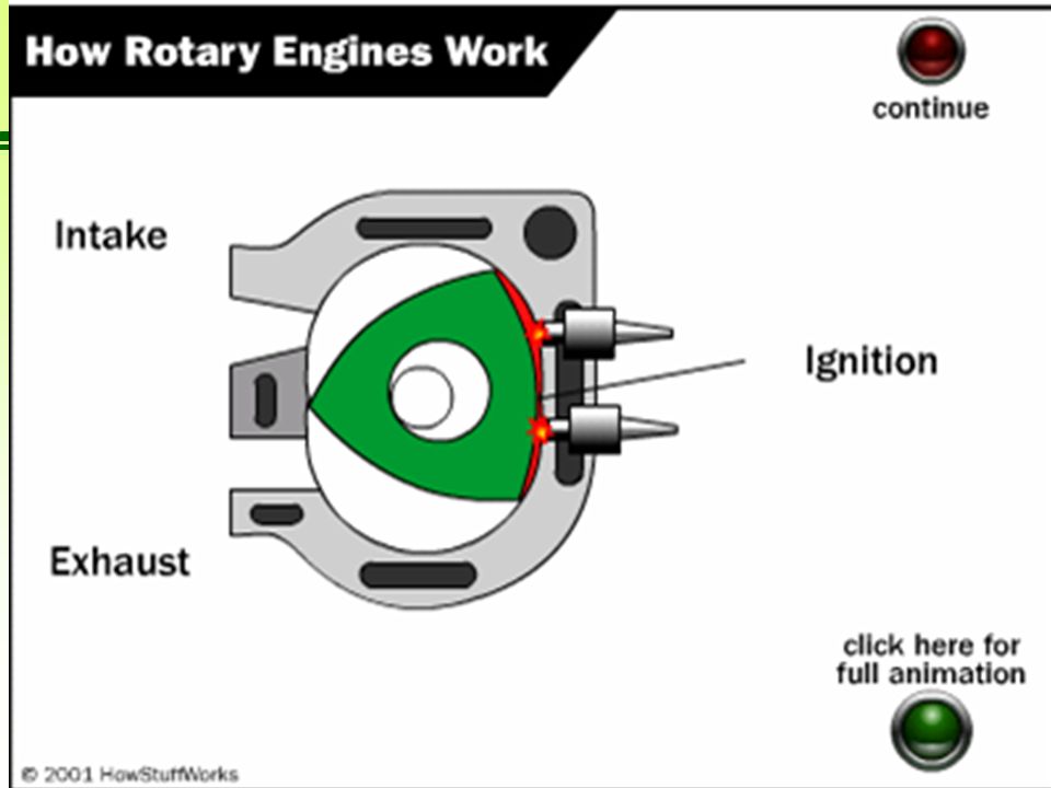
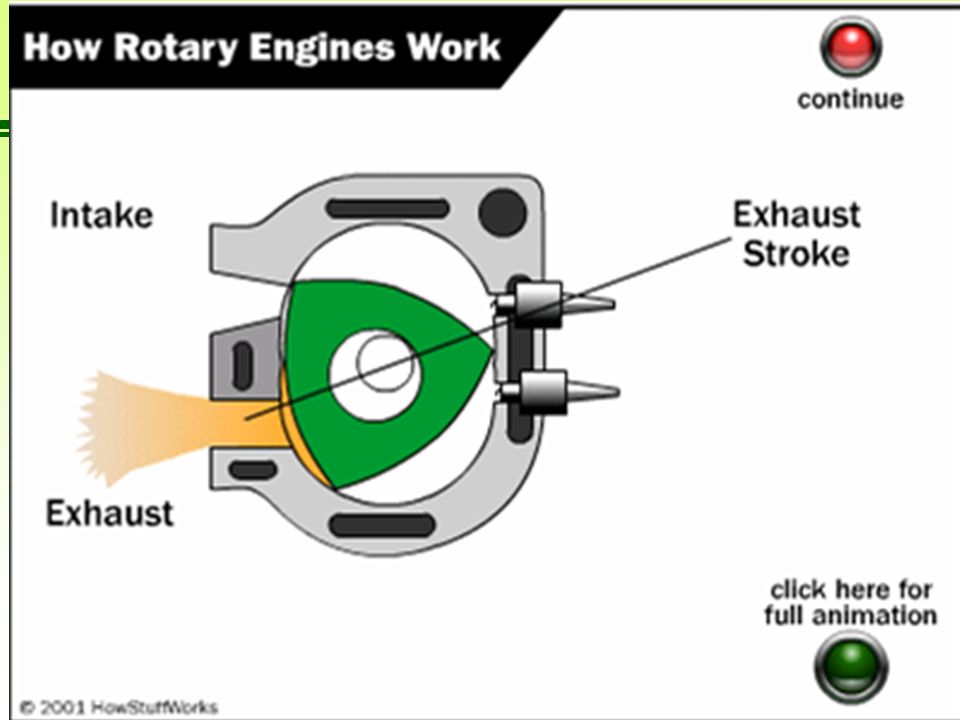
This presentation created by former ENGR 100 students Sam Henry, Thomas Munsey, Grayson Deitering, Daniel Munro Wankel Rotary Engine Smoother Engine is continuously moving in one direction rather than changing direction like in piston engines. Slower Main moving parts move slower which increase the reliability of the engine. Fewer Moving Parts The rotary engine consists of three main moving parts while a piston engine contains at least 40 moving parts. Challenges Passing the US Emissions tests. Manufacturing costs are higher. Consumes more fuel.

Similar presentations