Download presentation
Presentation is loading. Please wait.

2
Small Engine Fundamentals
Chapter 4 Small Engine Fundamentals Four-Stroke Cycle Theory • Four-Stroke Cycle Engine Operation • Engine Components and Functions • Small Engine Systems • Compression Systems • Fuel Systems • Ignition Systems • Lubrication and Cooling Systems • Governor Systems • Electrical Systems • Braking Systems

3
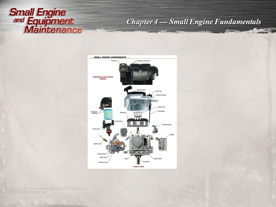
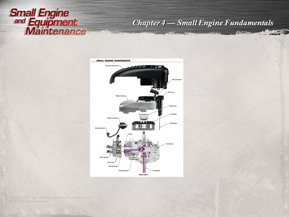
Gasoline-powered four-stroke cycle engines typically power lawn mowers, snow throwers, lawn and garden tractors, and many other types of outdoor power equipment. The four-stroke cycle engine is the most common type of small engine. A four-stroke cycle engine is an internal combustion engine that uses four piston strokes (intake, compression, power, and exhaust) to complete one operating cycle. Gasoline-powered four-stroke cycle engines power many types of equipment, such as lawn mowers, snow throwers, and lawn and garden tractors, by generating the precise amount of power required to perform work. See Figure 4-1. Most small engine components can be easily accessed.
 to complete one operating cycle. Gasoline-powered four-stroke cycle engines power many types of equipment, such as lawn mowers, snow throwers, and lawn and garden tractors, by generating the precise amount of power required to perform work. See Figure 4-1. Most small engine components can be easily accessed.")
4
Small engines are designed to perform simple tasks with specific types of outdoor power equipment.
Small engines are commonly designed for simple tasks such as cutting lawns and turning soil. See Figure 4-2. Unlike engines for automobiles and other vehicles that frequently accelerate, decelerate, or idle for long time periods, small engines typically run at constant speed. They change speed in response to modest changes in load such as when a lawn mower is pushed over a patch of thick grass.

5
A four-stroke cycle engine completes five events in one operating cycle, including intake, compression, ignition, power, and exhaust events. Five events are completed in one operating cycle. An operating cycle includes intake, compression, ignition, power, and exhaust events. It requires two revolutions (720°) of the crankshaft. See Figure 4-3. A four-stroke cycle engine operates through the following procedure. 1. The rewind starter cord is pulled, or electric starter pushbutton depressed, causing the engine to rotate and allowing precise amounts of fuel and filtered air to mix in the carburetor. 2. The fuel and filtered air mixture rushes into the engine to be compressed, ignited, and burned in a controlled process known as internal combustion. Internal combustion produces hot rapidly expanding gases. …Complete list on pages 38–39.
 of the crankshaft. See Figure 4-3. A four-stroke cycle engine operates through the following procedure. 1. The rewind starter cord is pulled, or electric starter pushbutton depressed, causing the engine to rotate and allowing precise amounts of fuel and filtered air to mix in the carburetor. 2. The fuel and filtered air mixture rushes into the engine to be compressed, ignited, and burned in a controlled process known as internal combustion. Internal combustion produces hot rapidly expanding gases. …Complete list on pages 38–39.")
6
An intake event is an engine operation event in which an air-fuel mixture is introduced to a combustion chamber. An intake event is an engine operation event in which an air-fuel mixture is introduced to a combustion chamber. See Figure 4-4. The mixture of air and fuel is introduced into the combustion chamber during an intake stroke. The intake valve is open and the piston moves from top dead center (TDC) to bottom dead center (BDC).
 to bottom dead center (BDC).")
7
A compression event is an engine operation event in which a trapped mixture of air and fuel is compressed inside the combustion chamber. A compression event is an engine operation event in which a trapped air-fuel mixture is compressed inside a cylinder. See Figure 4-5. Compression occurs as the piston travels toward TDC. The air-fuel mixture is compressed for a more efficient burn and to allow energy to be released faster when the mixture is ignited. The engine is able to do work because the energy required for compression—and stored in the flywheel—is far less than the force produced during combustion. In a typical small engine, compression requires one-fourth the energy produced during com-bustion. The surplus energy drives the power stroke.

8
An ignition event is an engine operation event in which a charge is ignited and rapidly oxidized through a chemical reaction to release heat energy. An ignition (combustion) event is an engine operation event in which fuel is ignited to release heat energy. See Figure 4-6. Combustion is a rapid, oxidizing chemical reaction in which a fuel chemically combines with atmospheric oxygen and releases energy in the form of heat. Proper combustion involves a short but finite time to spread a flame throughout a combustion chamber. The spark at the spark plug initiates combustion at approximately 20° of crankshaft rotation before top dead center (BTDC).
 event is an engine operation event in which fuel is ignited to release heat energy. See Figure 4-6. Combustion is a rapid, oxidizing chemical reaction in which a fuel chemically combines with atmospheric oxygen and releases energy in the form of heat. Proper combustion involves a short but finite time to spread a flame throughout a combustion chamber. The spark at the spark plug initiates combustion at approximately 20° of crankshaft rotation before top dead center (BTDC).")
9
A power event is an engine operation event in which a compressed charge is ignited and hot expanding gases force a piston head away from a cylinder head. A power event is an engine operation event in which a compressed charge is ignited and hot expanding gases force a piston head away from a cylinder head. See Figure 4-7. The intake and exhaust valves of the engine are closed. At approximately 20° BTDC, the spark plug initiates combustion, creating a flame that burns the compressed air-fuel mixture. The hot gases produced by combustion have no way to escape, so they push the piston away from the cylinder head. The motion is transferred through the connecting rod to apply torque to the crankshaft.

10
An exhaust event is an engine operation event in which spent gases are removed from the com-bustion chamber and released to the atmosphere. An exhaust event is an engine operation event in which spent gases are removed from a combustion chamber and released to the atmosphere. See Figure 4-8. As the piston reaches BDC during the power stroke, the power stroke is completed. The exhaust valve opens, allowing the piston to evacuate exhaust as it moves, once again, toward TDC. With the chamber cleared of exhaust, the piston reaches TDC. An entire cycle is complete.

11
Basic small engine components are used for starting, running, and stopping the engine.
All small engines have the same basic components that perform the same functions. These components are used for starting, running, and stopping the engine. See Figure 4-9. Small engines include the following basic components: • fuel tank: A fuel tank is a vessel connected to an engine for the purpose of holding fuel, such as gasoline or diesel fuel, to power the engine. Fuel tanks can be composed of sheet metal or plastic and, depending on the size of the engine, can hold 1/2 gal. to 5 gal. of fuel. • shroud: A shroud is a rigid, protective cover attached to an engine near the fuel tank to protect the engine from moisture, dust, dirt, and other debris. …Complete list on pages 44–45.

14
Valve location determines whether an engine is an L-head or overhead valve engine.
The location of valves determines the type of head design and the necessary components for the valve train. In an L-head engine, the valves are located in the cylinder block on one side of the cylinder. Although over-head valve and direct overhead valve (DOV) engines are installed on some modern types of OPE, most small engines are L-head engines. See Figure 4-10.
 engines are installed on some modern types of OPE, most small engines are L-head engines. See Figure")
15
A piston acts as the movable end of the combustion chamber by using the forces and heat created during engine operation. A piston is a cylindrical engine component that slides back and forth in a cylinder bore by forces produced during the combustion process. See Figure The piston rides through a cylinder bore, much as a plunger rides through the chamber in a hand-operated air pump. At the appropriate moment, the cylinder bore is sealed so that the air-fuel mixture is compressed as the piston moves toward the cylinder head. When the mixture is ignited, rapidly expanding gases force the piston back down through the cylinder bore.

16
Piston rings provide a seal between the piston and the cylinder bore and commonly include a compression ring, wiper ring, and oil control ring. The piston rings commonly used on small engines include a compression ring, wiper ring, and oil control ring. A compression ring is a piston ring located in the ring groove closest to a piston head. The compression ring seals the combustion chamber against any leakage that occurs during the combustion process. A wiper ring is a piston ring with a tapered face located in the ring groove between the compression ring and oil ring. The wiper ring is used to further seal the combustion chamber and to wipe the cylinder wall clean of excess oil. Combustion gases that pass by the compression ring are stopped by the wiper ring. The wiper ring is used to further seal the combustion chamber and to wipe the cylinder wall clean of excess oil. Combustion gases that pass by the compression ring are stopped by the wiper ring. The oil control ring provides a precise amount of oil for the compression and wiper ring to ride on. The oil control ring also provides an exit for the excess oil on the cylinder wall to return to the crankcase. See Figure 4-12.

17
A crankcase houses and supports the crankshaft of an engine.
A crankcase is an engine component that houses and supports a crankshaft. In a four-stroke cycle engine, the crankcase also acts as an oil reservoir for the lubrication of engine components. The crankcase may be a part of the engine block or a separate component. Some crankcases consist of multiple parts such as a sump or crankcase cover. See Figure 4-13.

18
A typical small engine fuel system includes a fuel tank, fuel pump (on some models), fuel filter, carburetor, and fuel line. A fuel system typically includes a fuel tank, fuel pump, fuel filter, carburetor, and fuel line. To burn, gasoline must be converted from a liquid to a vapor. The vapors that burn in a small engine are formed from a mixture of air and fuel. The correct amount of air and fuel must be mixed together to maintain the required engine speed. The best method used to locate the com-ponents of a fuel system is to begin at the fuel tank and trace back through the system. See Figure The repairs most commonly made for a small engine are on the fuel system.

19
A carburetor provides the required air-fuel mixture to a combustion chamber based on engine operating speed and load. It is the fully sealed, low-pressure area above the piston that causes the carburetor to draw in the two components the engine requires for combustion. Carburetion occurs when air speed increases at the venturi and air pressure drops. Since fluids flow from areas of high pressure to low pressure, fuel from the bowl or tank is drawn into the throat, mixing with air to form a combustible vapor. See Figure 4-15.

20
A throttle plate is used to regulate the flow of the air-fuel mixture to an engine, while a choke plate is used only to assist in cold starting. At one end of the carburetor throat is a throttle plate. A throttle plate is a disk that pivots on a movable shaft to regulate the air and fuel flow in a carburetor. The throttle plate is connected to a control lever (often referred to as a throttle) and opens or closes to increase or decrease engine speed. As the throttle plate opens, air is drawn into the carburetor. Airflow, in turn, determines how much fuel is delivered for combustion. See Figure 4-16. A choke plate is a flat plate placed in a carburetor body between the throttle plate and air intake that is used to restrict airflow to help start a cold engine.
 and opens or closes to increase or decrease engine speed. As the throttle plate opens, air is drawn into the carburetor. Airflow, in turn, determines how much fuel is delivered for combustion. See Figure A choke plate is a flat plate placed in a carburetor body between the throttle plate and air intake that is used to restrict airflow to help start a cold engine.")
21
An ignition system includes multiple magnets, an ignition armature, a spark plug lead, and a spark plug. An ignition system is the starting system for a small engine. Whether the engine is started by pulling a rewind rope or turning a key (switch) on an electric starter motor, the ignition system produces a precisely timed spark inside the combustion chamber. The ignition system includes magnets mounted on the surface of the flywheel, an ignition armature mounted adjacent to the flywheel containing copper wire windings, a spark plug lead attached to the armature, and a spark plug. See Figure 4-17.
 on an electric starter motor, the ignition system produces a precisely timed spark inside the combustion chamber. The ignition system includes magnets mounted on the surface of the flywheel, an ignition armature mounted adjacent to the flywheel containing copper wire windings, a spark plug lead attached to the armature, and a spark plug. See Figure")
22
Breaker points control the flow of electricity to other parts of the ignition system circuit.
A breaker point ignition system functions similarly to a solid-state ignition. However, a breaker point ignition system uses a mechanical switch, rather than a transistor, to close the electrical circuit required to produce a high-voltage spark at the spark plug tip. The breaker points remain separated for most of the four-stroke cycle. A flat spot machined into the crankshaft causes one of the breaker points to pivot temporarily, closing the gap between the two and closing the circuit. The other point is retained by a spring and is mounted on a pivot. The points are held open by a point plunger. See Figure 4-18.

23
A solid-state ignition system has a solid-state transistor in the ignition armature.
A solid-state ignition system requires 10,000 V to 20,000 V of electric pressure to produce a spark at the tip of a spark plug. To produce the required electric pressure in modern OPE, a solid-state transistor is used in the ignition armature. During each pass of the flywheel magnets with the solid-state transistor laminations, the transistor establishes an electrical circuit (also referred to as closing a circuit). The circuit produces 2 A to 3 A of current. The current is then converted to high-voltage power that travels through the spark plug lead to the spark plug. See Figure 4-19.
. The circuit produces 2 A to 3 A of current. The current is then converted to high-voltage power that travels through the spark plug lead to the spark plug. See Figure")
24
The lubrication system and its engine oil absorb heat energy and transfer it to the aluminum cylinder block. The cooling air can then absorb the heat energy from the aluminum and transfer it into the atmosphere. The lubrication and cooling systems on small air-cooled engines are linked together. Although air passing over the aluminum cylinder, crankcase, and cylinder head carries a portion of the combustion heat energy away from the engine, the lubrication system transfers a significant portion of the heat. Most small engines have an oil dipper that provides the motion to distribute engine oil. The lubrication system and engine oil absorb heat energy and transfer it to an aluminum cylinder block. The cooling air around the cylinder block then absorbs the heat energy from the aluminum and transfers it into the atmosphere. See Figure 4-20.

25
A governor system is an engine system that maintains a desired engine speed regardless of the load applied to the engine. A governor system is an engine system that maintains a desired engine speed regardless of the load applied to the engine. See Figure A governor system is comparable to the cruise control system of an automobile. It keeps the engine running at the selected speed, regardless of changes in the load.

26
A mechanical governor uses the gears and flyweights inside a crankcase as speed-sensing devices to detect changes in a load and adjusts the throttle accordingly. A mechanical governor is an engine governor that adjusts a throttle as needed by using the gears and flyweights inside a crankcase as speed-sensing devices to detect changes in a load. See Figure When operating a small engine under a light load, the carburetor must deliver a relatively small amount of air-fuel mixture to the combustion chamber. As the crankshaft rotates, centrifugal force causes the flyweights to open.

27
A pneumatic governor uses a movable metal or plastic air vane as a speed-sensing device by registering the change in air pressure around a rotating flywheel. A pneumatic governor is an engine governor that uses a movable metal or plastic air vane as a speed-sensing device to detect changes in a load. It accomplishes this by registering the change in air pressure around the rotating flywheel. See Figure The design of a pneumatic governor is simpler than that of a mechanical governor, and its parts are easier to access. However, the design of the pneumatic governor is slightly less reliable, since small particles of debris can interfere with its operation.

28
A small engine electrical system typically consists of an alternator, rectifier, regulator, and 12 V battery. Batteries are installed on some OPE, similar to automotive batteries, to operate components such as lamps, motors, and engine starters. When an engine uses the energy stored in a battery for starting, it relies on an electrical system to maintain battery strength. The electrical system of a small engine typically consists of an alternator, rectifier, regulator, and 12 V battery. See Figure 4-24.

29
An electrical system can be set up to produce either alternating current (AC) or direct current (DC). An electrical system can be designed to produce either alternating current (AC) or direct current (DC). Alternating current (AC) is current flow that reverses direction at regular intervals. Direct current (DC) is current that flows in one direction only. See Figure 4-25.
 or direct current (DC). Alternating current (AC) is current flow that reverses direction at regular intervals. Direct current (DC) is current that flows in one direction only. See Figure")
30
Small engine braking systems include several components that are designed to stop an engine quickly.
The braking system of a modern small engine protects the user and others in the area from the moving parts of unattended equipment. The system is designed to stop the engine and disengage the blade or other moving parts any time the controls are released or the operator exits the equipment such as a ride-on lawn mower. Small engine braking systems include a stop switch and stop switch wire, brake bracket, brake pad, brake spring, brake anchor, cable, brake bail, and throttle stop switch. See Figure 4-26.

Similar presentations