Download presentation
Presentation is loading. Please wait.

1
Lec.16 Underground pipeline irrigation system - structures for underground pipelines.

2
UNDERGROUND PIPELINE IRRIGATION DISTRIBUTION SYSTEM
An underground pipeline water distribution system consists of buried pipes for conveying water to different points on the farm and allied structures required for the efficient functioning of the system.

3
ADVANTAGES Cultivation can be done above the pipeline No culverts or other structures are required Saves land area. The pipelines do not interfere with farming operations. Long life and low maintenance costs. Eliminates water loss by evaporation. Operate under pressure and can be laid uphill or downhill, thus permitting the delivery of irrigation water to areas not accessible by open channels. Wells need not be located at the highpoint of the farm but may be at a location that provides best water supply. Water pumped from wells may be delivered directly into the pipeline system.

4
DISADVANTAGES Under ground pipeline irrigation distribution systems have a higher initial cost Difficult to locate leakages and repair is costly Needs techanical man power for installation

5
PIPES TYPES Reinforced concrete pipes Factory-made reinforced concrete pipes Vitrified clay pipes Asbestos cement pipes Plastic or PVC pipes

7
DISCHARGE CAPACITY = Q = AV
By re-writing the Darcy’s equation V = (2Hdg / f L)1/2 In which A = Area of cross section of the pipe in m2 V = velocity of flow of water through the pipe, m/sec. H = available head causing flow in m d = diameter of pipe in m g = acceleration due to gravity m/sec2 L = length of pipe, m f = Darcy’s roughness coefficient
1/2. In which. A = Area of cross section of the pipe in m2. V = velocity of flow of water through the pipe, m/sec. H = available head causing flow in m. d = diameter of pipe in m. g = acceleration due to gravity m/sec2. L = length of pipe, m. f = Darcy’s roughness coefficient.")
8
PUMP STAND The inlet structure Minimum inner dia. = 60 cm
Foundation concrete = 15 cm Free board = 30 cm Buried pipe 10 cm above concrete and 45 cm below soil surface Pipe inlet covered by mesh to prevent debris entry It should be tall enough to create required hydraulic head

10
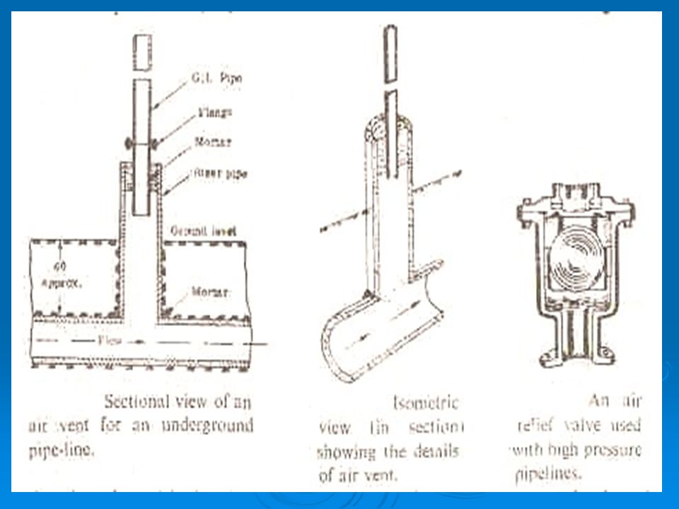
Air vent Provided to release the entrapped air from the system
The dia. of riser pipe should be minimum of d/2 as buried pipe upto 60 cm above soil surface There after the dia. can be reduced upto 5 cm to reduce cost 60 cm free board should be given Provided at all points of change of direction of flow Provide at every 150 m on the straight line

12
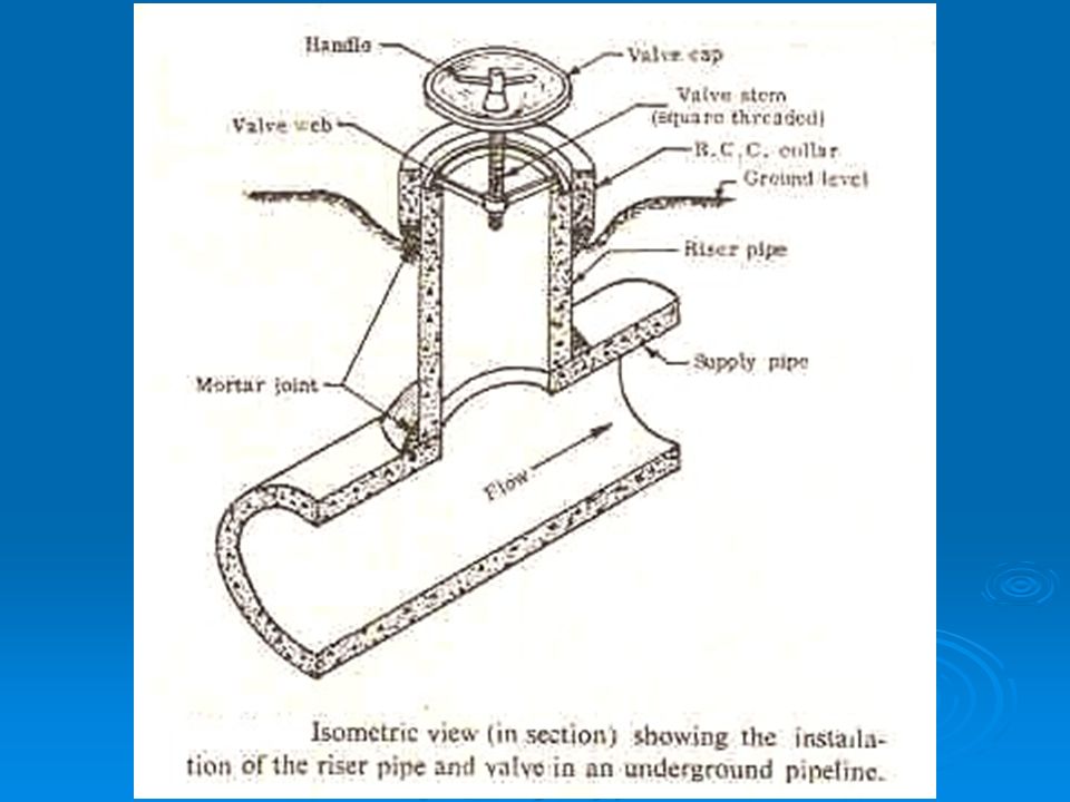
Riser valve – alfalfa valve
Provided at outlet points The structure has a threaded valve stem fitted on a bracket The valve plate is raised or lowered with a handle The valve plate seats on a rubber washer/ valve seat making a leak proof set up

14
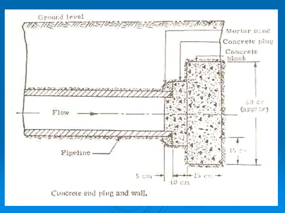
End plug It is provided at all closing points of pipe line
The plug protrudes in side the pipe for about 10 to 15 cm The end of the plug should be supported sufficiently to with stand the operating pressure

15
INSTALLATION OF CONCRETE PIPELINES
Proper installation of the pipe is the key to trouble-free service The process of laying the pipeline Selection of depth and grade of laying, Digging to proper length and grade, Lowering the pipe and squeezing, Sealing the joints, and Backfilling the trench.

Similar presentations


. Sewer Basics Collection and transport of wastewater from each home/building to the point where treatment occurs.>")

.>")
. 2. Waterway-Waterway (syphon or.>")


