Download presentation
Presentation is loading. Please wait.

1
COMPUTED TOMOGRAPHY I – RAD 365 CT - Scan
Prepared By: Ala’a Ali Tayem Abed

3
Tomography History ● Tomos = slice; Graphein = to write
● Definition - imaging of an object by analyzing its slices. History ● mathematical theory of tomographic image reconstructions (Johann Radon). ● conventional tomography (A. Vallebona). ● theoretical basis of CT (A. McLeod Cormack). ● first commercial CT (Sir Godfrey Hounsfield). ● first 3rd generation CT. ● Nobel price (Cormack & Hounsfield). ● single-row CT. ● double-row spiral CT. ● row spiral CT. ● row spiral CT. Nobel man ... Godfrey Hounsfield with an early version of the CT scanner, then called the EMI Scanner.
. ● conventional tomography (A. Vallebona). ● theoretical basis of CT (A. McLeod Cormack). ● first commercial CT (Sir Godfrey Hounsfield). ● first 3rd generation CT. ● Nobel price (Cormack & Hounsfield). ● single-row CT. ● double-row spiral CT. ● row spiral CT. ● row spiral CT. Nobel man ... Godfrey Hounsfield with an early version of the CT scanner, then called the EMI Scanner.")
4
Introduction In conventional X-ray imaging, the entire thickness of the body is projected on a film: structures overlap and are difficult to distinguish). One of the problems is the loss of information about depth. Computed tomography (CT) is a method of acquiring and reconstructing the image of a thin cross section on the basis of measurements of attenuation. In comparison with conventional radiographs, CT images are free of superimposing tissues and are capable of much higher contrast due to elimination of scatter. What is CT? • CT is a Medical imaging device which generates Cross sectional images used to aid in diagnosis of various diseases. A CT Scanner is… CT: Computerized Tomography CAT: Computerized Axial Tomography Spiral CT. Multi-Slice CT or Multi-Detector. CT Volume.
. One of the problems is the loss of information about depth. Computed tomography (CT) is a method of acquiring and reconstructing the image of a thin cross section on the basis of measurements of attenuation. In comparison with conventional radiographs, CT images are free of superimposing tissues and are capable of much higher contrast due to elimination of scatter. What is CT • CT is a Medical imaging device which generates Cross sectional images used to aid in diagnosis of various diseases. A CT Scanner is… CT: Computerized Tomography. CAT: Computerized Axial Tomography. Spiral CT. Multi-Slice CT or Multi-Detector. CT Volume.")
5
Slice / Cut The cross sectional portion of the body which is scanned for the production of CT image is called a slice. The slice has width and therefore volume. The width is determined by the width of the x-ray beam.

6
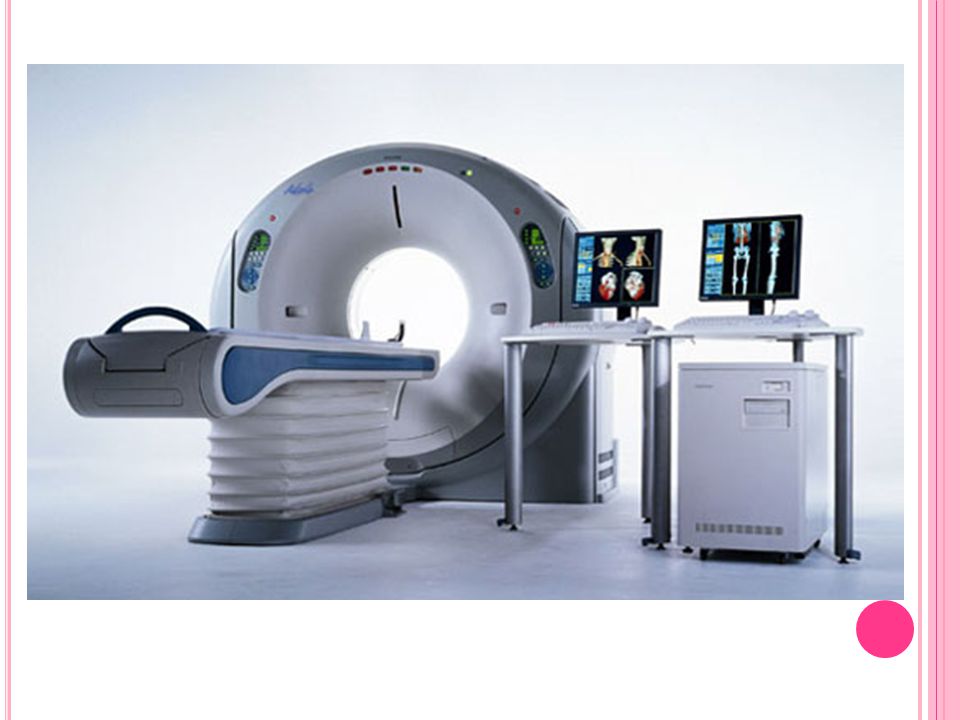
Computed Tomography Components
Gantry. X-Ray Tube. Detector. Table.

7
CT Scanner Design There are three basic tube- detector projection systems: Parallel – Beam System. Fan – Beam System. Cone – Beam System.

8
Generations Definition of Generation First Generation
Classification of computed tomography (CT) based upon: Arrangement of components and Mechanical Motion required to collect data. First Generation Design: single X-ray source and single X-ray detector cell to collect all the data for a single slice. Source and detector, rigidly coupled. Source/detector rotate slightly. Beam: Pencil beam translated across patient to obtain set of parallel projection measurements at one angle. Process is repeated once for each projection angle until 180 projections , across a 24 cm FOV. Translation and rotation process, this geometry is referred to as a translate/rotate scanner. very slow ( 5 min / slice ).
 based upon: Arrangement of components and Mechanical Motion required to collect data. First Generation. Design: single X-ray source and single X-ray detector cell to collect all the data for a single slice. Source and detector, rigidly coupled. Source/detector rotate slightly. Beam: Pencil beam translated across patient to obtain set of parallel projection measurements at one angle. Process is repeated once for each projection angle until 180 projections , across a 24 cm FOV. Translation and rotation process, this geometry is referred to as a translate/rotate scanner. very slow ( 5 min / slice ).")
9
EMI Mark I scanner (1973). Contrast resolution of internal structures was unprecedented, images had poor spatial Resolution.

10
(1st) First Generation
 First Generation")
11
1st CT Generation Image

12
Second Generation Design: multiple detectors. Beam: Fan Beam, X-ray source emits radiation over a large angle. Source and array of detectors are translated. Multiple projections obtained during each traversal past the patient, this scanner is significantly more efficient and faster than 1st one. This generation: a translate/rotate scanner. Pros: reducing scan time. Early versions: 3 detectors each displaced by1°. Later versions: up to 53 detectors; First designs to permit scans of the trunk.

13
(2nd) Second Generation CT
 Second Generation CT")
14
Third Generation Design: larger array Of detectors
( ) detectors, usually circular. Shorter scanning time (2 sec). Designers: pure rotational scanning motion could be used. Beam: Fan Beam, X-ray tube is collimated to a wide x-ray beam (fan-shaped ). Tube and detector array rotate around patient. Rotate - Rotate Designs. Different projections are obtained during rotation. Improvement in detector and data acquisition technology; Detector array with enough, high spatial resolution cells to allow measurement of a fan-beam projection of entire patient cross-section.
 detectors, usually circular. Shorter scanning time (2 sec). Designers: pure rotational scanning motion could be used. Beam: Fan Beam, X-ray tube is collimated to a wide x-ray beam (fan-shaped ). Tube and detector array rotate around patient. Rotate - Rotate Designs. Different projections are obtained during rotation. Improvement in detector and data acquisition technology; Detector array with enough, high spatial resolution cells to allow measurement of a fan-beam projection of entire patient cross-section.")
15
(3rd) Third Generation
 Third Generation")
16
Fourth Generation Design: stationary detector ring & rotating X-ray tube. Circular array of FIXED detectors. Source only rotates within a stationary ring of detectors. Larger fan beam. Shorter scanning time. Early versions: had some 600 detectors. Later versions: had up to 4,800.

17
(4th) Fourth Generation
 Fourth Generation")
19
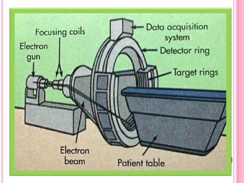
Electron Beam Tomography (EBT) (5th Generation CT Scanner)
Design: x-ray tube is a large ring that circles patient, opposed to detector ring. Use: for Cardiac Tomographic Imaging “Cine CT”. X -rays produced = High - Energy Electron Beam. It is capable of 50 millisecond scan times and can produce 17 slices /second. stationary/stationary geometry . X-Ray Tube.

21
Spiral (Helical) Scanners - (6th Generation)
In conventional CT the tube & detectors moves clock wise & anti-clock wise 360°, while in spiral / helical CT the tube & detector arrays continuously move with the table. Single – Slice Spiral CT Scanner ( SSCT ). Multi – Slice Spiral CT ( MSCT ).
. Multi – Slice Spiral CT ( MSCT ).")
22
What is pitch? Pitch is the distance in millimeters that the table moves during one complete rotation of the X-ray tube, divided by the slice thickness (millimeters). Increasing the pitch by increasing the table speed reduces dose and scanning time, but at the cost of decreased image resolution.
. Increasing. the pitch by increasing the table speed reduces dose and scanning time, but at the. cost of decreased image resolution.")
23
Pitch = Table Movement per Rotation
Beam Collimation (Essentially a measure of Relative Speed) • Contiguous Spiral Pitch = 1 (10 mm / 10 mm) • Extended (Non-Contiguous) Spiral Pitch = 2 (20 mm/ 10 mm) • Overlapping Spiral Pitch = 1/2 ( 5 mm / 10 mm)
 • Contiguous Spiral. Pitch = 1 (10 mm / 10 mm) • Extended (Non-Contiguous) Spiral. Pitch = 2 (20 mm/ 10 mm) • Overlapping Spiral. Pitch = 1/2 ( 5 mm / 10 mm)")
24
Cone Beam Spiral CT ( CBCT ) - (7th Seventh Generation).
Design: (multiple detector array): With multiple detector array scanners, slice thickness is determined by detector size, not by the collimator. Possible to increase width of detector array to 16 or even 320 elements. Allowing simultaneous acquisition of up to 256 adjacent image slices. Faster, higher resolution scanning.
: With multiple detector array scanners, slice thickness is determined by detector size, not by the collimator. Possible to increase width of detector array to 16 or even 320 elements. Allowing simultaneous acquisition of up to 256 adjacent image slices. Faster, higher resolution scanning.")
25
Generation Source Source Collimation Detector
1st Single X-ray Tube Pencil Beam Single 2nd Fan Beam (not enough to cover FOV) Multiple 3rd Fan Beam (enough to cover FOV) Many 4th Fan Beam covers FOV Stationary Ring of Detectors 5th Many tungsten anodes in single large tube Fan Beam 6th 3G/4G 7th Cone Beam Multiple array of detectors
 Multiple. 3rd. Fan Beam (enough to cover FOV) Many. 4th. Fan Beam covers FOV. Stationary Ring of. Detectors. 5th. Many tungsten anodes in single large tube. Fan Beam. 6th. 3G/4G. 7th. Cone Beam. Multiple array of. detectors.")
26
Thank You Best Wishes For All

Similar presentations


 theory was developed 1972: The CT scan was invented by Godfrey.>")


 of radiation directed toward the pt. and the remnant radiation emitted from the pt.>")

