Download presentation
Presentation is loading. Please wait.

1
Selecting, Operating, and Maintaining Electric Motors
Instructional Materials Service Texas A&M University 8795

2
Advantages of Using Electrical Motors

3
Economical Operation: can work continuously and take the place of 2 or more laborers
Dependable: always ready to work Efficient: efficiency ranges from 65 to 95 percent Long Life: 20 to 30 years with proper care Ease of Operation: special skills not required Safe: if properly used

4
Low Service Requirement: minimum amount of attention required
Quiet Operation: when properly applied and installed Automation: can be automatically and remotely controlled Adaptable: light, compact, easily moved Available: throughout the country; standard bases, sizes, wiring equipment, etc.

5
Calculating Cost of Operation & Service Factors

6
“West Virginia” Relationship:
Watts = Volts X Amps (W=VA) Standard “rule of thumb”: electric motors consume 746 watts of electricity per 1 Hp of work produced Power Factor (PF): A ratio of calculated power to actual power Used by electric utilities High PF = customer uses inefficient motors in their processes Power Factor Relationship: Watts consumed = Volts X Amps X PF PF = W ÷ (VA) More accurate
 Standard rule of thumb : electric motors consume 746 watts of electricity per 1 Hp of work produced. Power Factor (PF): A ratio of calculated power to actual power. Used by electric utilities. High PF = customer uses inefficient motors in their processes. Power Factor Relationship: Watts consumed = Volts X Amps X PF. PF = W ÷ (VA) More accurate.")
7
Other “Rules of Thumb” Fractional horsepower motors:
Rated at less than 1 Hp Estimate 1200 W/Hp or PF of 1.2 Single-phase motors (1 Hp or more): Use approximately 1000 W/Hp or PF of 1.0 Three-phase motors: Estimated at 800 W/Hp or PF of 0.8
: Use approximately 1000 W/Hp or PF of 1.0. Three-phase motors: Estimated at 800 W/Hp or PF of 0.8.")
8
Cost Calculation Problem
Figure the cost of pumping 2000 gallons of water with a ¼ Hp motor if it pumps 500 gallons per hour and the cost is 8 cents/KWH. 2000 gallons ÷ 500 gallons/hour = 4 hours operating time ¼ Hp = approximately 300 watts (1200 watts per Hp ÷ 4) (300 watts X 4 hours) ÷ 1000 watts/KW = 1.2 kilowatt-hours (KWH) used 1.2 KWH X 8 cents/KWH = 9.6 or 10 cents cost for pumping 2000 gallons of water
 (300 watts X 4 hours) ÷ 1000 watts/KW = 1.2 kilowatt-hours (KWH) used. 1.2 KWH X 8 cents/KWH = 9.6 or 10 cents cost for pumping 2000 gallons of water.")
9
Service Factor (S.F.) Amount of overload the motor can tolerate on a continuous basis at rated voltage and frequency 1.0 S.F.: no overload is tolerated for extended periods 1.25 S.F.: motor can be overloaded 25% for an extended period of time when operated at rated voltage and frequency Common service factors for AC (alternating current) motors: 1.15, 1.20, 1.25, 1.35 & 1.4
 motors: 1.15, 1.20, 1.25, 1.35 & 1.4.")
10
Efficiency Calculation (Using a S.F.)
A 0.5 Hp electric motor is able to move 3000 pounds of potting mixture into a storage bin. The motor has a S.F. of 1.2, and an output of 550 watts. Is this motor capable of performing this task?

11
0.5 Hp X 746 watts/Hp = 373 watts 550 W ÷ 373 W = 1.47, or an additional 47% output is needed to move the potting mixture 0.5 Hp X 1.2 S.F. = 0.6 Hp output The motor can only produce 0.6 Hp (an additional 20 %) for a limited time. 0.5 Hp X 1.47 = Hp of output needed This motor would burn up before it moved all the potting mix.
 for a limited time. 0.5 Hp X 1.47 = Hp of output needed. This motor would burn up before it moved all the potting mix.")
12
Is a ¾ Hp motor with a S. F. of 1
Is a ¾ Hp motor with a S.F. of 1.2 and a 550-watt output capable of performing the task efficiently? 0.75 Hp X 746 = 559 watts 550 watts ÷ 559 watts = 0.98 (98%-round to 100) YES, the motor is suited to the task
 YES, the motor is suited to the task.")
13
Factors To Consider In Selecting Electric Motors

14
A motor must do three things:
1. Start the equipment load 2. Drive the load once it is started 3. Survive the abuse of the surroundings in which it operates

15
Type of Power Available
230-volt motor should not be used if only 115-volt circuits are available Three-phase motor cannot be operated on electrical system with only single-phase service Typical Operating Voltages: Single-Phase Three-phase 115 208 230 460 240 480

16
Size of Motor Rated in Hp
Refers to the power that it will develop when the motor is turning at full speed “Rules of Thumb” for estimating size needed: If equipment can be operated by hand, a 1/4 Hp motor will usually be adequate If gasoline engine is to be replaced by electric motor, an electric motor approximately 2/3 the Hp rating of the engine will be adequate Replace tractor PTO with an electric motor of approximately the same Hp

17
Starting Load Motor selected must produce adequate starting torque to start the load Commonly–used motors: Split phase Capacitor start-induction run Capacitor start-capacitor run Repulsion start-induction run Series or universal Shaded pole Three-phase Capacitor start-induction run & Three-phase are the most common and produce highest starting torque

18
Speed Requirement Rated at the speed the shaft will turn in revolutions per minute (rpm) when motor is operating at full speed Rpm of motor should be speed needed to operate equipment at proper speed

19
Bearing Type Sleeve bearings OR Anti-friction bearings
Require less maintenance and can be mounted in any position

20
Base Type Rigid base Sliding adjustable base Cushion mount
Reduces vibration & wear Determined by application of motor

21
Environment Provide proper protection from surroundings
Typical motor enclosures: Open drip proof Splash proof Totally enclosed-fan cooled (TEFC) Explosion proof Totally enclosed-air over (TEAO) Totally enclosed-non ventilated (TENV)
 Explosion proof. Totally enclosed-air over (TEAO) Totally enclosed-non ventilated (TENV)")
22
Power Availability

23
Motor must be located on properly sized electrical circuit and service entrance to function efficiently In some situations, motor should be only major load on the circuit

24
Service Entrance Amperage & Wiring
Motor Size Service Entrance Amperage & Wiring Voltage Phase 1/3 hp or less 30 A; 2-wire 120 V Single 1/3 hp-1½ hp 30 A; 3-wire V 1½ hp-5hp 60 A; 3-wire 5 hp-7½ hp 100 A; 3-wire Over 7 hp Over 100 A; 4-wire V Three Two-wire: one conductor & one neutral wire Three-wire: two conductors & one neutral wire Four-wire: three conductors & one neutral wire

25
Types of Bearings Used in Electric Motors

26
Sleeve Bearings A bushing that must be pressed into the motor housing
Diameter of motor shaft is 0.001” smaller than sleeve bearing Adequate to hold a film of oil between the shaft and bearing Designed for axial loads

28
Advantages: Disadvantage:
Initial cost of motor is less than one with anti-friction bearings Less expensive to replace Used on very large (500 Hp) A.C. motors Disadvantage: Motor must be mounted horizontally to allow for even, gravity force flow of oil Oil flows along grooves and into window to lubricate bearing
 A.C. motors. Disadvantage: Motor must be mounted horizontally to allow for even, gravity force flow of oil. Oil flows along grooves and into window to lubricate bearing.")
30
Anti-friction Bearings
Used with heavy alignment loads Made up of two separate races Separated by many round roller balls Outer race is stationary in end ball Inner race is firmly pressed onto motor shaft Inner race turns, the balls roll & outer race stands still Used to meet the specific demands of the load being driven If motor is not properly aligned, excessive bearing wear will result

32
Three types: Must be removed from housing to be lubricated
Can remain intact and be lubricated through a filler tube with a grease gun Sealed bearing—must be replaced rather than lubricated Found in motors used in difficult locations

33
Advantages: Motors can be mounted in any position
Tend to roll more easily and create less drag on the motor Used exclusively on motors, except for fractional Hp small blower motors such as hair dryers

35
Motor Mountings

36
A motor must be securely mounted to drive a piece of equipment.
Mounts for electric motors come in a variety of styles, each serving a different purpose and application.

37
Rigid Base Resilient Base

39
Motor Enclosures

40
Motors must operate in all kinds of environments.
The environment in which the motor is placed helps to dictate the type of enclosure of the motor.

41
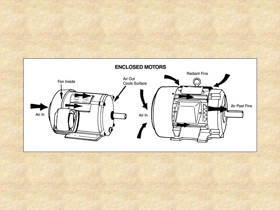
Two types: Open Enclosure: Totally Enclosed:
Allow movement of air through it to help in cooling May not be used in any situation where moisture or explosive dust or gases are present Totally Enclosed: Have fins on the housings to provide radiant and convection cooling Must use a higher degree of insulation on windings to prevent overheating Should be used on all motors in animal confinement situations

42
Typical motor enclosures:
Open Drip-proof (ODP) Totally-enclosed fan-cooled (TEFC)—used in outdoor or dirty applications Totally-enclosed air-over (TEAO)—used in grain handling applications Totally-enclosed non-ventilated (TENV)—used in milk pumps and similar applications Explosion-proof
 Totally-enclosed fan-cooled (TEFC)—used in outdoor or dirty applications. Totally-enclosed air-over (TEAO)—used in grain handling applications. Totally-enclosed non-ventilated (TENV)—used in milk pumps and similar applications. Explosion-proof.")
45
Motor Nameplate Information

46
The nameplate provides information that will assist a person in selecting the proper motor for the job, in making installation, and in energizing the motor with proper voltage.

48
Universal Electric Motor: indicates that this is a standard replacement motor
Thermally Protected: motor is equipped with devices designed to disconnect the current flow if insulating materials become too hot SER 12P 14666J: manufacturer’s serial number MOD HE3E207N: manufacturer’s model number STK. NO. 619: manufacturer’s stock number VOLTS : motor can operate on either 208 or 230 volts HZ 60: frequency for which the motor is designed to operate

49
AMPS 1.2: motor draws 1.2 amperes when operating at full load capacity
RPM-1025: indicates motor turns 1025 revolutions per minute when pulling its rated load PH1: motor runs on single-phase power CAP5MFD370VAC: motor is equipped with a continuous-operation run capacitor, rated at 5 microfarads and 370 volts AC INS CL B: motor has class B insulation, providing protection up to 130oC (266oF) AMB 60oC: motor is rated to work at an ambient of 60oC (140oF)
 AMB 60oC: motor is rated to work at an ambient of 60oC (140oF)")
50
AO: air-over ventilation is used to cool this motor
HP-1/5: motor is designed to pull a 1/5 Hp load when operated at the rated voltage and cycle CONT: continuous duty Motor will pull rated load under rated conditions continuously and not overheat May have INT: intermittent duty; rated for 5, 15, 30, or 60 minute operating times AO: air-over ventilation is used to cool this motor ROT REV: indicates direction of rotation of the shaft BRG SLV: motor has sleeve bearings

52
TYPE FH: indicates motor is a fractional-horsepower motor
FRAME A48: designation that gives motor dimensions based on NEMA standards Two-digit frame numbers ÷ 16 = distance in inches from centerline of shaft to foot of base TYPE FH: indicates motor is a fractional-horsepower motor SF 1.35: indicates motor will tolerate a 35% overload for extended periods SFA 3.5: number of amps the motor will draw when operating at the SF load of 1.35 times the rated Hp HSG OPEN: indicates type of motor enclosure CONNECTIONS: wiring diagrams for installation or changing direction of rotation

53
Types & Uses of Common Electric Motors

54
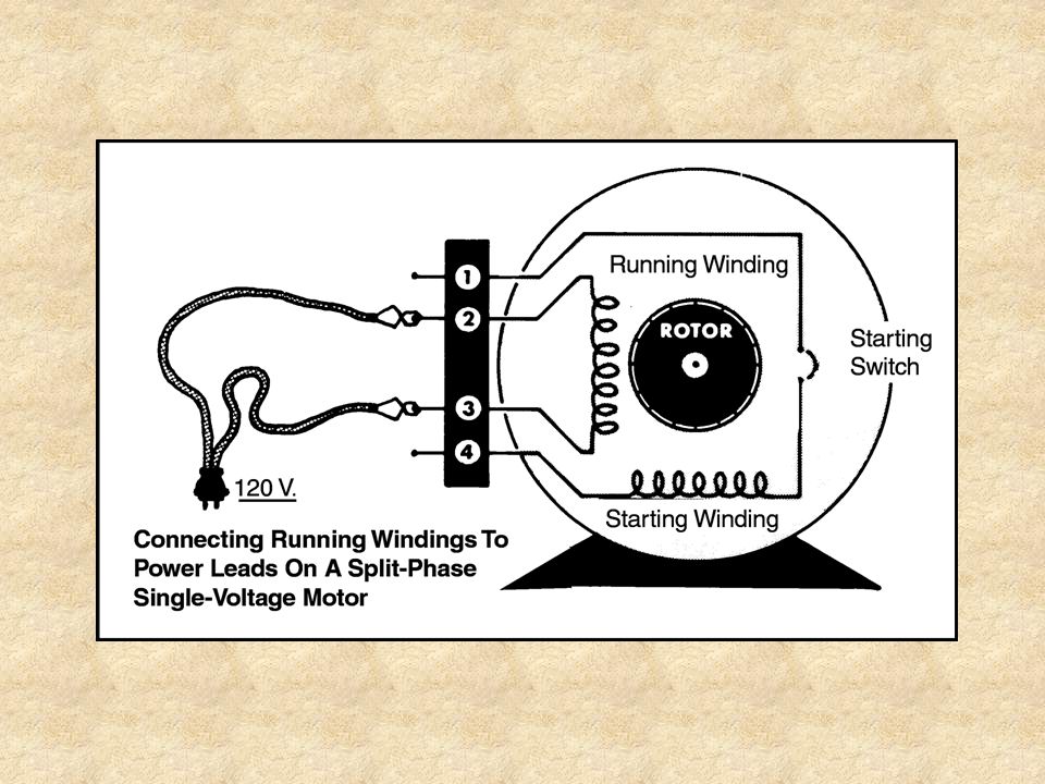
Split-Phase Motor Used for starting loads such as fans, bench grinders, laundry equipment, and machinery tools Has a high starting current requirement and will draw 5-7 times its normal running current when starting Primarily single voltage motors

56
As motor reaches 80% of its running speed, starting switch opens and stops flow of current through the starting winding Continuity: the presence of a path for electrical current flow, or a “complete” circuit Can be determined in each winding using a digital multimeter (DMM)
")
58
When power leads are connected to ends of running winding, motor will hum
When power leads are connected to ends of starting winding, motor will start and stop as centrifugal mechanism closes and opens starting switch

60
To operate motor, one end of starting and running windings are attached to one lead and the other ends of both windings are attached to the other lead To reverse rotation of shaft, ends of starting windings are changed with respect to running windings leads

62
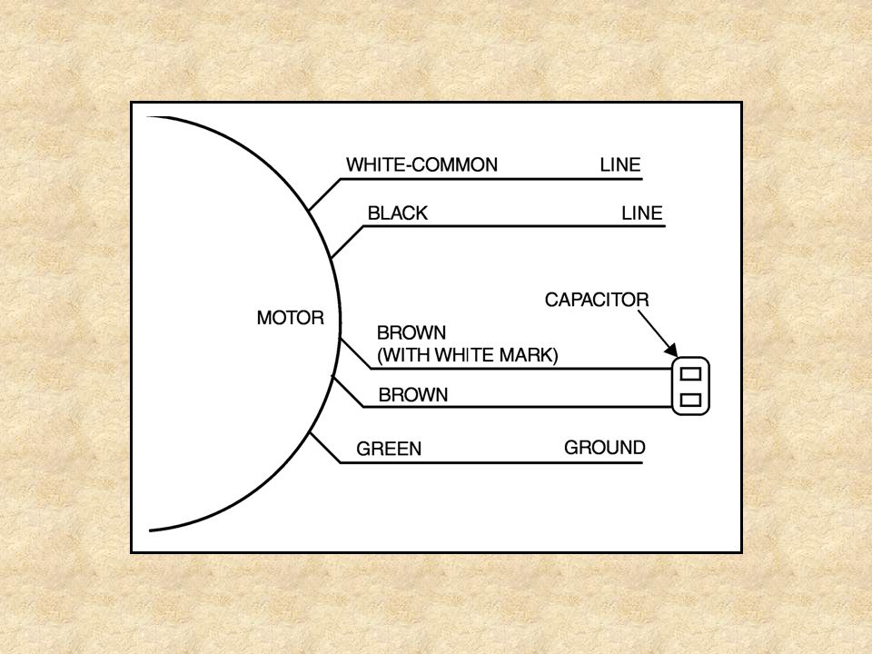
Capacitor-Start Motor
Used for difficult starting loads Has a capacitor in the starting winding to give the motor more starting torque Has a “medium” starting current requirement Will draw 3 to 6 times its normal running current when starting

63
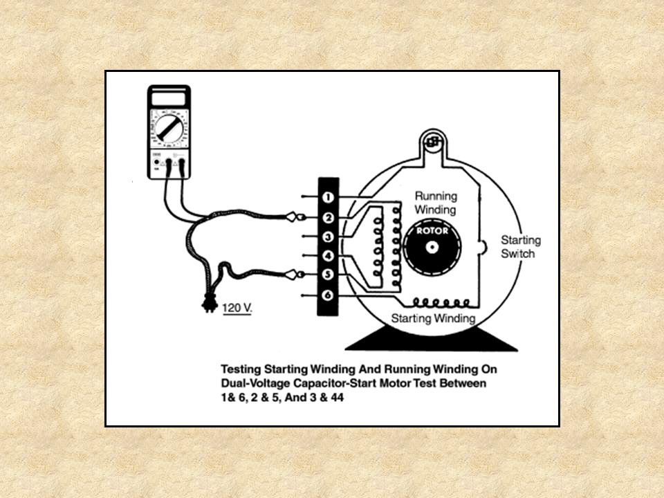
When approximately 75% of full load speed has been reached, centrifugal relay opens set of switch contacts in start-winding circuit Removes capacitor and starting winding from the operating or running circuit Power consumption returns to normal rated level Constant speed motor Range of operation = rpm Sizes = ⅛ - 10 Hp

64
Single or dual voltage motor
Single = starting winding and running winding Dual = starting winding and two running windings To identify starting winding, remove capacitor cover and use the DMM set in continuity test mode to check between leads one or six and capacitor terminals

67
Running windings are wired in parallel

69
Running windings are wired in series

71
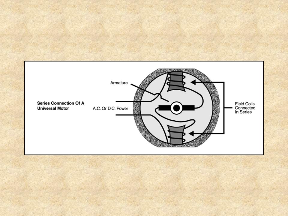
Universal or Series Motor
Special purpose motor Usually a part of portable appliances or tools Can be operated on AC or DC Designed for intermittent use, variable speed, and may be reversible Has a high starting torque & a high starting current Sizes = 1/150 – 2 Hp

73
Shaded-Pole Motor Small, single-phase motor Operates on AC
Low starting torque Low efficiency Sizes = 1/20 – 1/6 Hp Not reversible except by reversing field coils Used for light duty

75
Permanent Split-Capacitor (PSC) Motor
Used when a load requires a higher starting torque than a shaded-pole motor can produce Very efficient Manufactured with higher Hp ratings than shaded-pole motors

78
Three-Phase Motor Operated only on three-phase AC
Medium to high starting torque Low-, normal-, or high-starting current requirement Designed for self-starting applications Has no starting-winding

79
Sizes = 1/3 – several hundred Hp 1 Hp & larger:
Constant-speed motor Sizes = 1/3 – several hundred Hp 1 Hp & larger: Commonly used in industry Less expensive to purchase & operate than single-phase motors Last longer, fewer parts & fewer reliability problems

82
Motor Drives

83
Classification of Drives:
Selecting a Drive: Consider operating speed of equipment & size of drive Classification of Drives: Direct: Motor connected directly to a machine Machine operates at same speed as motor Flexible Shaft Drive, Flexible Hose Coupling Drive, Cushion-Flange Coupling Drive, Flange Coupling Drive Speed Conversion (belts & pulleys): Used to power machines and equipment at speeds different from that of the drive motor V-belt, Webbed multi-V-belt, V-flat drive
: Used to power machines and equipment at speeds different from that of the drive motor. V-belt, Webbed multi-V-belt, V-flat drive.")
84
Flexible Shaft Drive Used on equipment operating at various angles
Manufactured to operate in only one direction Machine with this drive operates at same speed as motor

86
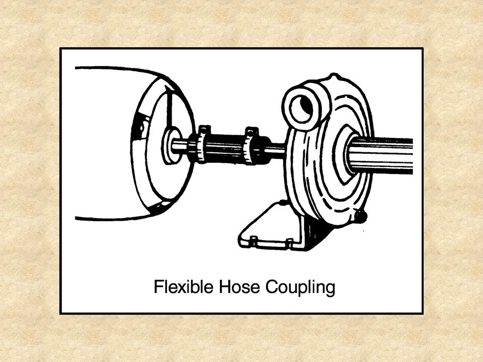
Flexible Hose Coupling Drive
Piece of plastic or rubber hose is used as the drive Ends of hose are forced over ends of machine and motor shaft and held in place with clamps

88
Cushion-Flange Coupling Drive
Consists of two flanges attached to the shafts and a flexible center part fastened to the flanges Center is made of rubber or similar material Furnishes a flexible action

90
Flange Coupling Drive Consists of two metal discs and a flexible middle disc

92
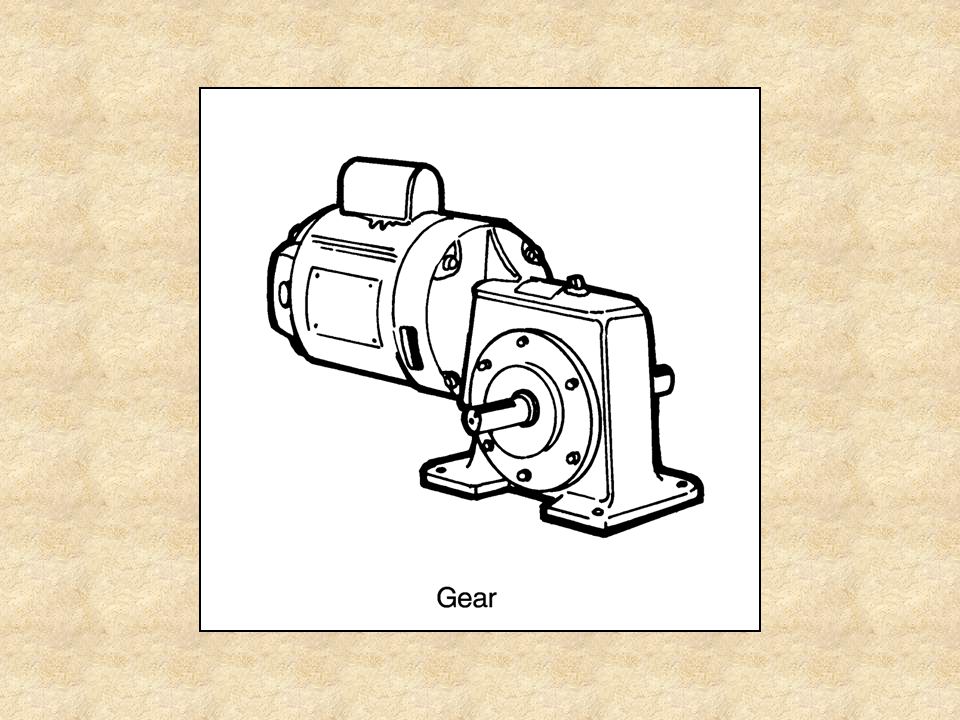
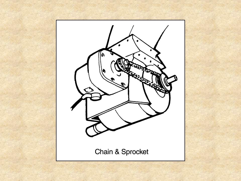
Gear & Chain-and-Sprocket Drives
Generally included as a part of the machinery Relatively complex

95
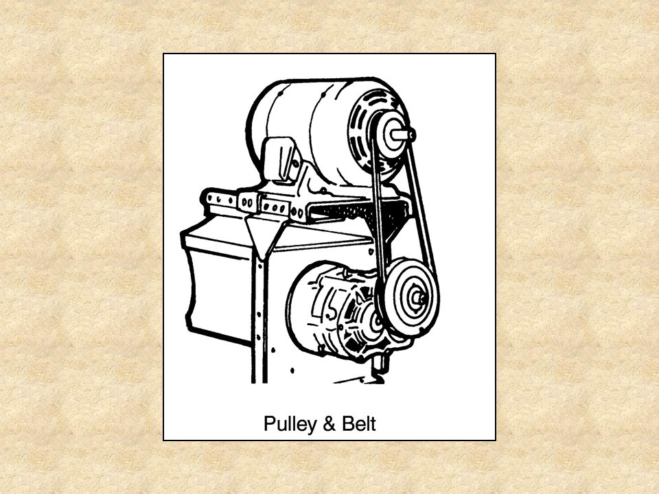
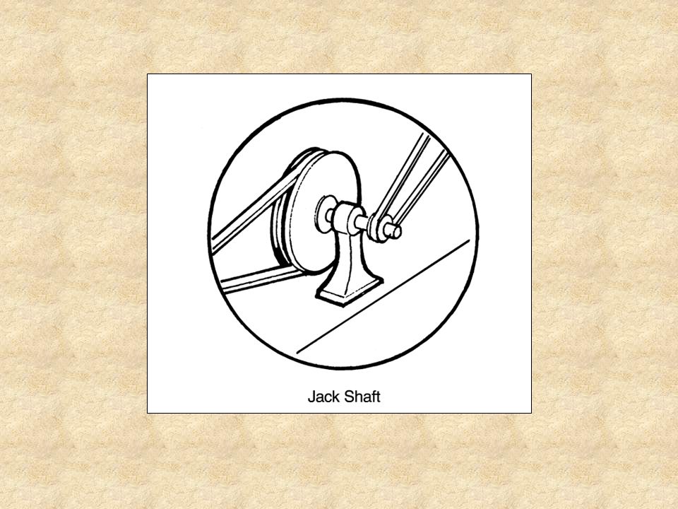
Pulley-and-Belt Drives
Very common and easy to install Larger pulleys prevent slippage better To prevent slippage: Motors ½ Hp or less, use at least a 2” diameter pulley Motors larger than ½ Hp, use a 3” diameter pulley Jackshaft: Shaft with a pulley on both ends Recommended as part of the drive for equipment designed to operate at less than 200 rpm Pulley connecting jackshaft to motor should be 12” in diameter Common types: V-belt, Webbed Multi-V-belt, V-flat drive

98
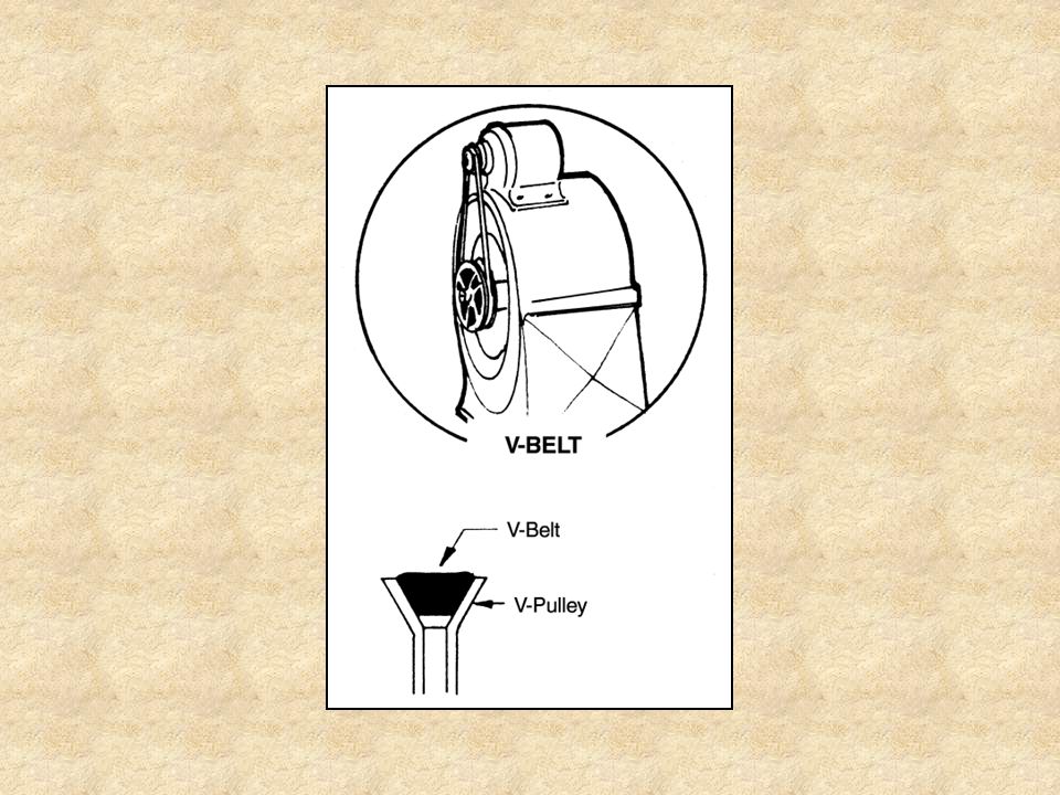
V-Belt Most popular drive used with electric motors Advantages:
Motor may be mounted on or close to machine Less tension is needed on the belt Belt stays on pulley better Very common on cooling fans and squirrel-cage blowers

100
Three sizes: FHP: A-Section: B-Section:
suited for pulleys 2½” and less in diameter, on motors of less than 1 Hp Thinner & more flexible than other V-belts A-Section: Heavier and can be used on small pulleys More slippage than the thinner belt Stiffness of belt prevents it from following curvature of pulleys Designed for pulleys 3” in diameter or larger, on motors from ¾ Hp to 5 Hp B-Section: Designed for use on motors of 3 Hp or larger, with a motor pulley 5½” or larger in diameter

102
Webbed Multi-V-Belt Made up of two or more V-belts webbed together
Main Advantages: Elimination of slippage Belt turnover

104
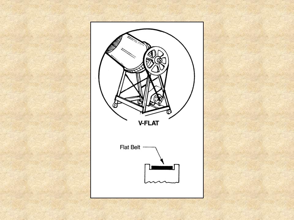
V-Flat Belt Drive Consists of one or more V-belts, one V-pulley, and one flat pulley Recommended for machines with pulleys larger than 12” in diameter and operated at 600 rpm or less To prevent belt slippage: Distance from center of motor pulley to center of machine pulley should not be greater than diameter of equipment pulley

106
V-pulleys Standard V-pulley: V-step pulley: Adjustable V-pulley:
Used when only one speed is needed V-step pulley: Used for machine driven variable speeds Adjustable V-pulley: Also for variable speeds Diameter may be increased or decreased to adjust speed to desired rpm

108
Determining Length of a V-belt
Mounted Motor: Loop a piece of string around and in grooves of pulleys Pull tight Tie knots in the ends Cut string Measure length Gives inside length of belt needed

109
Unmounted Motor: 4 X diameter of largest pulley = ______
1.6 X diameter of motor pulley = _____ 1.6 X diameter of machine pulley = _____ Total Length = _________ Example: (motor pulley= 3”, machine pulley= 6”) 4 X 6 = 24.0 inches 1.6 X 3 = 4.8 inches 1.6 X 6 = 9.6 inches Closest standard length belt to the measurement should be purchased
 4 X 6 = 24.0 inches. 1.6 X 3 = 4.8 inches. 1.6 X 6 = 9.6 inches. Closest standard length belt to the measurement should be purchased.")
110
Determining Pulley Size
Working speed of machine: determined by size of machine pulley in relation to size of motor drive pulley Rule of Thumb: To increase speed of machine: reduce size of pulley on machine or place a larger pulley on motor shaft To decrease speed of machine: place a smaller pulley on motor shaft or a larger pulley on machine shaft

111
Pulley Size Formula: RPM of motor X Diameter of motor pulley = RPM of machine X Diameter of machine pulley Example 1: (Machine Pulley) 1/3 Hp electric motor Operates at 1750 rpm Need a pulley to turn a fan at 875 rpm What size pulley is needed on the fan if a 2” pulley is on the motor? 1750 X 2 = 875 X D (1750 X 2) ÷ 875 = D 3500 ÷ 875 = 4” pulley
 1/3 Hp electric motor. Operates at 1750 rpm. Need a pulley to turn a fan at 875 rpm. What size pulley is needed on the fan if a 2 pulley is on the motor 1750 X 2 = 875 X D. (1750 X 2) ÷ 875 = D ÷ 875 = 4 pulley.")
112
Example 2: (Machine Pulley)
1/3 Hp electric motor Operates at 1750 rpm Need a pulley to turn a compressor at 3500 rpm What size pulley is needed on the compressor if a 4” pulley is on the electric motor? 1750 X 4 = 3500 X D (1750 X 4) ÷ 3500 = D 7000 ÷ 3500 = 2” pulley
 ÷ 3500 = D ÷ 3500 = 2 pulley.")
113
Example 3: (pulley for a motor, jackshaft & machine)
Machine should operate at 60 rpm Motor speed is 1750 rpm Use a 2” pulley on a FHP motor Use a jackshaft with one pulley 12” in diameter and one 2” in diameter Step 1: Calculate speed of jackshaft Rpm (motor) X D (motor pulley) = rpm (jackshaft) X D (jackshaft pulley) 1750 X 2 = rpm (jackshaft) X 12 Rpm (jackshaft) = (1750 X 2) ÷ 12 = 292 rpm Step 2: Determine size of pulley for machine (292 rpm X 2” diameter of pulley) ÷ 60 rpm = 9.8” or 10” machine pulley
 X D (motor pulley) = rpm (jackshaft) X D (jackshaft pulley) 1750 X 2 = rpm (jackshaft) X 12. Rpm (jackshaft) = (1750 X 2) ÷ 12 = 292 rpm. Step 2: Determine size of pulley for machine. (292 rpm X 2 diameter of pulley) ÷ 60 rpm = 9.8 or 10 machine pulley.")
114
Switches & Control Devices

115
Switches

116
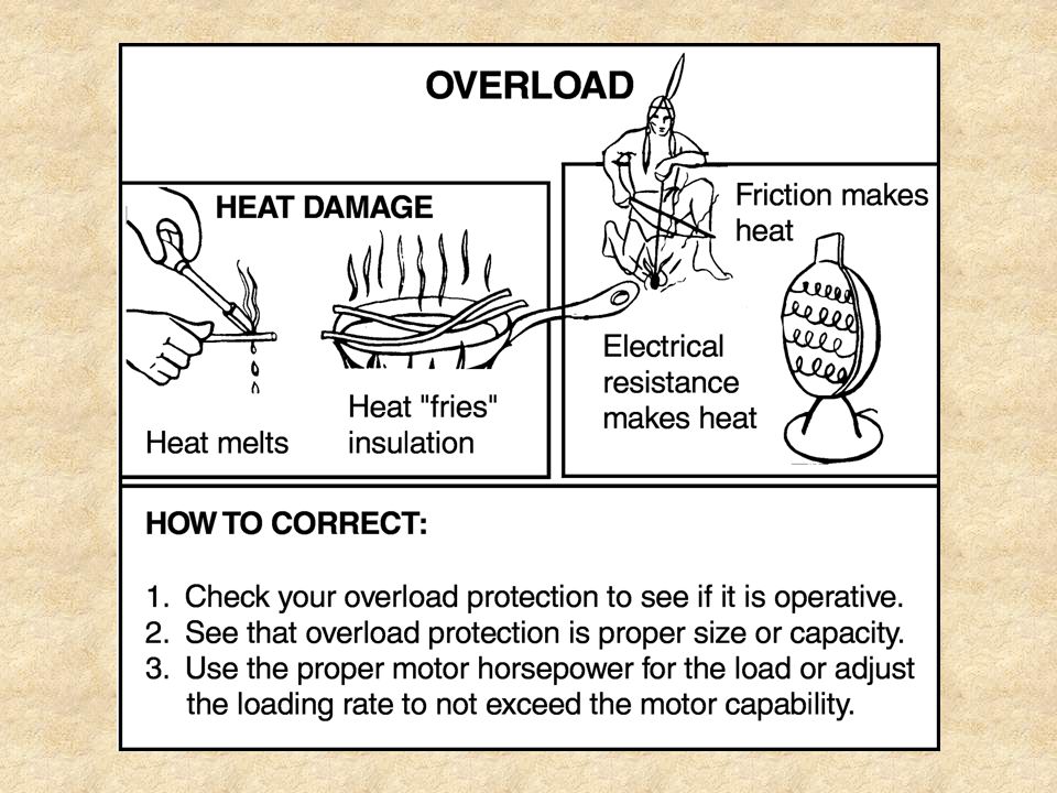
Overload Protectors Will automatically turn off motor or interrupt power supply if motor is pulling more amperage than it is designed to use Help prevent damage to motor which can result from overheating May be part of the switch or a fusible link in the power supply

119
Other Devices Humidistat: start and stop exhaust fans used in greenhouses Thermostat: similar to ones that regulate home air conditioners; control heater blowers during fall and winter months Timer: operate plant-watering systems at pre-determined intervals Float switch: activate sump pumps in lagoons and greenhouses

120
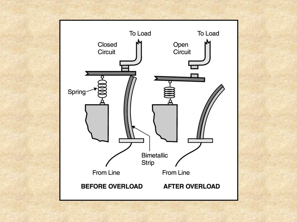
Flow Switches: Bi-metallic strip:
Used to monitor movement of gases or liquids Inform operator if an irrigation sprinkler or the ventilation system in a poultry house is operating and activates them when necessary Bi-metallic strip: Placed in series with run winding Elongates when too much current is being drawn by motor and causes contact points to open and motor stops Motors may have manual or automatic reset button that starts motor once strip has cooled

122
Magnetic Switches: used to start and stop large motors
Reset Buttons: Automatic: can be dangerous (motor may resume operation unexpectedly) Manual: Operator must consciously press button Should always be used in materials handling and feed transport systems Time Delay Fuses: used to support short-term, high amounts of current that are necessary to start some motors Magnetic Switches: used to start and stop large motors Drum Switches: used with motors that must run forward backward
 Manual: Operator must consciously press button. Should always be used in materials handling and feed transport systems. Time Delay Fuses: used to support short-term, high amounts of current that are necessary to start some motors. Magnetic Switches: used to start and stop large motors. Drum Switches: used with motors that must run forward backward.")
124
Operating Electric Motors

125
Once a motor has been wired and installed properly, operation is limited to safety precautions and turning on a switch.

126
Safety Precautions Visually inspect motor, pulleys, belts and machine to be driven for anything harmful Listen for strange noises, humming or tapping Smell to check for burning Feel motor housing to be sure it has not overheated Visually check to make sure motor is not vibrating excessively

127
Motor Protection and Maintenance

128
Overload Protection Overload caused by: Protection:
Motor size too small for job Improper wiring and low voltage Improper installation Belts too tight Improper lubrication Worn pulleys Clogging due to overloads Entry of foreign materials into motor Protection: Proper fusing of motor circuit Built-in protection in motor Manual reset switch control Special motor starter (current-limiting starter)
")
130
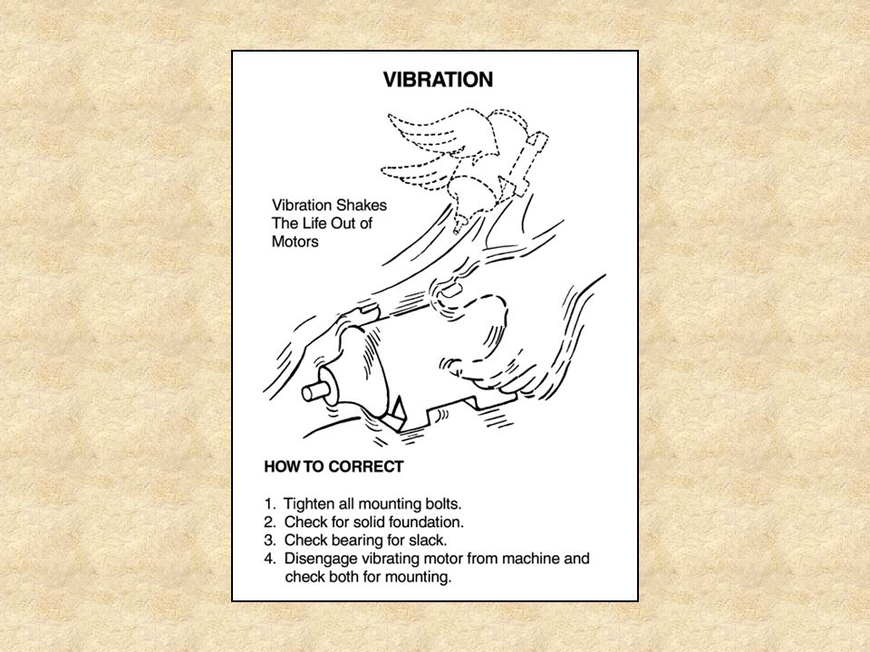
Proper Installation Minimum amount of vibration Proper alignment
Misalignment: Causes belt and bearing wear Will be a factor in overloading a motor

133
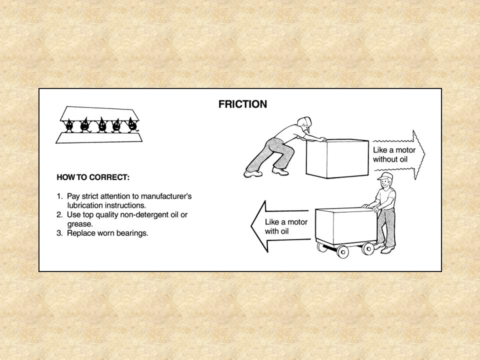
Decrease Friction Prevents excessive bearing wear and overloading
Manufacturer’s recommendations for lubrication intervals should be followed Use high-quality lubricant Motors with sleeve bearings must be mounted so shaft is horizontal & level Alignment of motor, drive,and equipment should be true

135
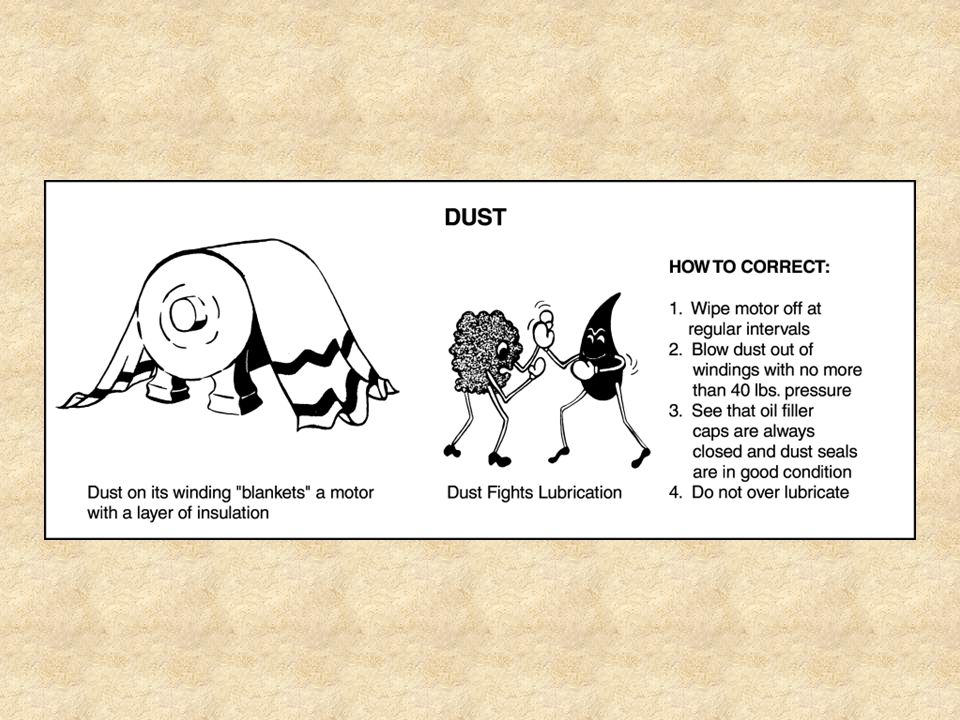
Protect From Excessive Oiling
Excess oil causes accumulation of extra dust or deterioration of insulation within motor

137
Protect From Dust Accumulation of dust in and on a motor acts as insulation and may cause excessive heating of the motor

139
Protect From Moisture Moisture is a conductor of electricity.
A wet motor should be dried thoroughly before it is used.

141
Preventive Maintenance
Check condition of bearings Check working path of motor, belts, and driven machine Check motor mount bolts and driven machine bolts Check belt connection between motor and driven machine Replace worn belts or pulleys

142
Safety Precautions for Removing & Disassembling a Motor
ALWAYS disconnect motor’s electrical power source before making any adjustments Discharge capacitor to prevent electrical shock Beware of moving parts. Necessary electrical repairs should be made by a qualified electrician. Remove and replace any safety guards.

143
The National Electrical Manufacturer’s Association (NEMA)
")
144
Formed by the merger of the Electric Power Club and the Associated Manufacturer’s of Electrical Supplies in 1926 Success story of the use and availability of electric motors is due in large part to NEMA Electrical manufacturers began working towards industry standardization during World War I At the time: Secretary of Commerce was Herbert Hoover Great Depression was three years away

145
Composed of over 500 member companies
Committed to advancing use of electric power through the standardization of electrical equipment Has resulted in a widely available, standardized supply of safe and efficient electrical supplies and equipment Composed of over 500 member companies Quality standards developed and promoted by NEMA influence: The Department of Defense (DOD) Underwriters Laboratories (UL) National Firer Protection Association (NFPA) NEMA Standards listed with the American National Standards Institute (ANSI)
 Underwriters Laboratories (UL) National Firer Protection Association (NFPA) NEMA Standards listed with the American National Standards Institute (ANSI)")
146
Nameplates: Found on every electric motor Result of standardization effort Ensures that the bases, wiring, protection and other factors will be the same in two similar motors even if produced by different manufacturers Information remains the same over a period of years Because of NEMA standards, motor replacement is not limited by brand name.

147
Trouble-Shooting Electric Motors

148
Trouble-shooting: the process of checking for a specific problem
When trouble-shooting an electric motor: Be sure motor is receiving correct voltage and frequency Check terminals to be sure correct voltage is getting to motor terminals Check for proper condition of all fuses and/or protective devices, especially reset button Check and secure all connections made on motor terminal plate Measure amperage draw of motor while operating and compare the reading with the percent of rated load figure on nameplate

149
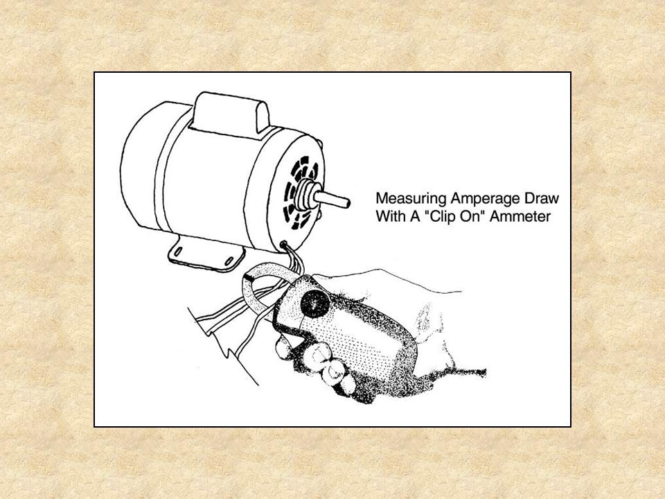
Both starting and running amperage draw can be checked with a clip-on or clamp-type ammeter.
Each conductor must be tested separately. Wear appropriate Personal Protective Equipment (PPE) when trouble-shooting motor problems.
 when trouble-shooting motor problems.")
152
Acknowledgements Kirk Edney, Curriculum Specialist, Instructional Materials Service, edited and reviewed this PowerPoint presentation Kristie Weller, Undergraduate Technician, Instructional Materials Service, organized and developed the information used in this PowerPoint presentation.

153
All Rights Reserved Reproduction or redistribution of all, or part,
of this presentation without written permission is prohibited. Instructional Materials Service Texas A&M University 2588 TAMUS College Station, Texas 2007

Similar presentations


>")


>")


