Download presentation
Presentation is loading. Please wait.

1
Part 1: Explain how the stability of an aeroplane is maintained
Uncontrolled copy not subject to amendment Principles of Flight Learning Outcome 2 Understand how the stability and manoeuvrability of an aeroplane are controlled Part 1: Explain how the stability of an aeroplane is maintained Revision 2.00

2
Principles of Flight Revision
A Bourne H Copter B Loons A Ship R Way C Tower Dan Winterland S Huttle I Flyum Revision

3
Questions for you …..

4
1. What is the force called that drives an aircraft forwards?
a. Lift b. Weight c. Drag d. Thrust

5
2. What is the force called that resists the forward motion of an aircraft?
a. Lift b. Weight c. Drag d. Thrust

6
3. If your speed is doubled, by how much would drag be increased?
a. x2 b. x4 c. x6 d. x8

7
4. If Thrust = Drag and Lift = Weight, then the aircraft is:
a. Climbing b. Flying straight and level and accelerating c. Flying straight and level and decelerating d. Flying straight and level at constant speed

8
Stability Objectives: Identify the axes of rotation for an aircraft
Identify the planes of movement for an aircraft Describe and explain stability in the three planes of movement 4. Explain dihedral and anhedral and how they affect stability

9
Planes of stabilisation
Yaw (Directional) Longitudinal Axis Normal Axis Pitch (Longitudinal) Lateral Axis Roll (Lateral) AXIS OF STABILITY All velocities are ANGULAR velocity Planes and Axes These are the terms used to describe the movement of an aircraft in 3 dimensions. Note that for now we are thinking of movement of the aircraft relative to itself - changes of its attitude - rather than it travelling through the air. Firstly, there are 3 axes about which an aircraft rotates; they all go through the centre of gravity, and they are all at 90° to each other. Similarly, there are 3 planes in which the aircraft moves (a plane in this sense is just a flat sheet or area). When an aircraft moves in one plane it rotates about an axis, and vice-versa. It can move in one, 2 or all 3 planes at the same time. The relationship between the planes and the axes are that the aircraft: a) Moves in the pitching plane (i.e. pitches) about its lateral axis b) Moves in the rolling plane (i.e. rolls) about its longitudinal axis c) Moves in the yawing plane (i.e. yaws) about its normal axis
 Longitudinal. Axis. Normal. Axis. Pitch. (Longitudinal) Lateral. Axis. Roll. (Lateral) AXIS OF STABILITY. All velocities are ANGULAR velocity. Planes and Axes. These are the terms used to describe the movement of an aircraft in 3 dimensions. Note that for now we are thinking of movement of the aircraft relative to itself - changes of its attitude - rather than it travelling through the air. Firstly, there are 3 axes about which an aircraft rotates; they all go through the centre of gravity, and they are all at 90° to each other. Similarly, there are 3 planes in which the aircraft moves (a plane in this sense is just a flat sheet or area). When an aircraft moves in one plane it rotates about an axis, and vice-versa. It can move in one, 2 or all 3 planes at the same time. The relationship between the planes and the axes are that the aircraft: a) Moves in the pitching plane (i.e. pitches) about its lateral axis. b) Moves in the rolling plane (i.e. rolls) about its longitudinal axis. c) Moves in the yawing plane (i.e. yaws) about its normal axis.")
10
Stabilisation Axis Longitudinal Plane Rolling Stability Lateral
AXIS OF STABILITY All velocities are ANGULAR velocity Stability in the Rolling Plane (Lateral Stability) 1. Dihedral Angle The wings of most aircraft are set into the fuselage at a slight upward angle to the horizontal called the dihedral angle. All or part of the wing may be inclined in this way, with the aim of making the aircraft laterally stable. If the wing drops in turbulent air, the lift force is no longer vertical and it no longer opposes the weight fully. Consequently, the aircraft begins to slip sideways, down towards the lower wing, and a side wind strikes it . The lower wing, because of its dihedral, meets the side wind at an angle - an angle of attack - which is greater than that of the upper wing. The lower wing therefore produces more lift than the upper wing and rolls the aircraft back until the wings are level. Another reason why the lift on the upper wing is less than that of the lower wing, is that it is shielded by the fuselage from some of the side wind, so not only is the angle of attack smaller on the upper wing, but also the airflow is slower. Many aircraft are designed with little or no dihedral, but they are nevertheless stable in roll because of this shielding of the upper wing. 2. Anhedral Angle Another stable design is the high wing aircraft, where the centre of gravity is well below the wing: here, the pendulum effect of the weight of the aircraft gives lateral stability. Some aircraft have quite a noticeable anhedral - wings inclined at a downward angle to the horizontal - which works on the same principle as dihedral, but with the opposite effect, creating lateral instability. This is the designer’s way of reducing the excessive lateral stability which can be encountered with “swept-back” wings.
 1. Dihedral Angle. The wings of most aircraft are set into the fuselage at a slight upward angle to the horizontal called the dihedral angle. All or part of the wing may be inclined in this way, with the aim of making the aircraft laterally stable. If the wing drops in turbulent air, the lift force is no longer vertical and it no longer opposes the weight fully. Consequently, the aircraft begins to slip sideways, down towards the lower wing, and a side wind strikes it . The lower wing, because of its dihedral, meets the side wind at an angle - an angle of attack - which is greater than that of the upper wing. The lower wing therefore produces more lift than the upper wing and rolls the aircraft back until the wings are level. Another reason why the lift on the upper wing is less than that of the lower wing, is that it is shielded by the fuselage from some of the side wind, so not only is the angle of attack smaller on the upper wing, but also the airflow is slower. Many aircraft are designed with little or no dihedral, but they are nevertheless stable in roll because of this shielding of the upper wing. 2. Anhedral Angle. Another stable design is the high wing aircraft, where the centre of gravity is well below the wing: here, the pendulum effect of the weight of the aircraft gives lateral stability. Some aircraft have quite a noticeable anhedral - wings inclined at a downward angle to the horizontal - which works on the same principle as dihedral, but with the opposite effect, creating lateral instability. This is the designer’s way of reducing the excessive lateral stability which can be encountered with swept-back wings.")
11
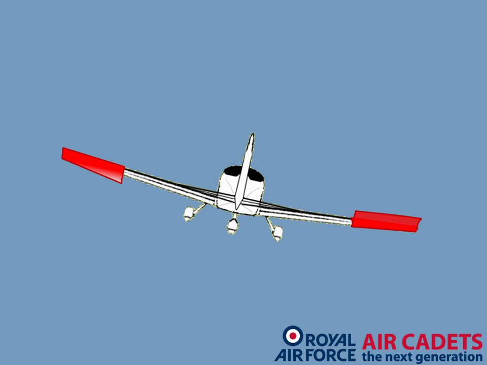
To create roll, the control column
is moved right Use of ailerons To roll the aircraft, the pilot uses the two moveable parts of the wings called ailerons. They also are linked to the stick, and conventionally are hinged to the trailing edges of each wing near the wing tips, where they have the most leverage about the centre of gravity. By moving the stick to the left, the pilot raises the left aileron and depresses the right. The left aileron thus has a reduced angle of attack and less lift. The extra upward force on the right wing and the reduced upward force on the left wing rolls the aircraft to the left about its longitudinal axis. It continues to roll until the pilot returns the stick to the central position, where the ailerons are again aligned with the wings surfaces. Note that if the aircraft were climbing or diving vertically, the roll to the left would take place just the same. For a roll to the right, the stick is moved to the right; the right aileron goes up, the left aileron down. “Stick to the right, roll to the right”, “Stick to the left, roll to the left”.

12
Left aileron down Right aileron up

13
The aircraft rolls right about the longitudinal axis

15
The aircraft rolls right and continues to do so until the control column is placed in the neutral position

16
Stabilisation Axis Longitudinal Lateral Plane Rolling Pitching
Stability Lateral Longitudinal AXIS OF STABILITY All velocities are ANGULAR velocity Stability in the pitching plane (Longitudinal Stability) As the tailplane is at the end of the fuselage, a long way from the centre of gravity, any forces on it will have great leverage. The tailplane is set to meet the local airflow at 0° angle of attack in cruising flight, and because it is cambered equally on both sides it produces no force up or down. If some disturbance, perhaps bumpy air in a cloud, jolts the aircraft into a tail-down attitude, the tailplane momentarily has an angle of attack to the oncoming air; consequently it produces lift which “levers” the aircraft back to a level position. If the aircraft is jolted nose down, the tailplane produces a downward force which levers the aircraft back into the level position, when once more the tailplane has no upward or downward force upon it. The aircraft is said to have stability in the pitching plane.
 As the tailplane is at the end of the fuselage, a long way from the centre of gravity, any forces on it will have great leverage. The tailplane is set to meet the local airflow at 0° angle of attack in cruising flight, and because it is cambered equally on both sides it produces no force up or down. If some disturbance, perhaps bumpy air in a cloud, jolts the aircraft into a tail-down attitude, the tailplane momentarily has an angle of attack to the oncoming air; consequently it produces lift which levers the aircraft back to a level position. If the aircraft is jolted nose down, the tailplane produces a downward force which levers the aircraft back into the level position, when once more the tailplane has no upward or downward force upon it. The aircraft is said to have stability in the pitching plane.")
17
To create pitch, the control column
is pushed forwards Use of elevators The pilot uses the elevators to make the aircraft’s nose pitch nose-down or nose-up. On most aircraft the elevators are two moveable parts of the tailplane, one on each side. On conventional aircraft they are hinged to the trailing edge of the tailplane where they have most leverage about the centre of gravity. They are linked to the pilot’s control column (usually called the “stick”). Moving it forward lowers the elevators, which then have an angle of attack – therefore lift - and the aircraft is levered tail up/nose - down about its lateral axis. If the pilot did this from the straight and level attitude, the aircraft would dive; if the pilot did it while in a vertical climb, the aircraft would turn towards the level position. Pitching continues as long as the elevators are deflected, and it stops when the pilot centralises the stick, such that the elevators again lie flush with the tailplane. Moving the control column backwards of course, has the opposite effect. “Stick back, nose up”, “Stick forward, nose down” - always remembering that “up” and “down” are measured solely in relation to the pilot, and not to the world outside the aircraft.
. Moving it forward lowers the elevators, which then have an angle of attack – therefore lift - and the aircraft is levered tail up/nose - down about its lateral axis. If the pilot did this from the straight and level attitude, the aircraft would dive; if the pilot did it while in a vertical climb, the aircraft would turn towards the level position. Pitching continues as long as the elevators are deflected, and it stops when the pilot centralises the stick, such that the elevators again lie flush with the tailplane. Moving the control column backwards of course, has the opposite effect. Stick back, nose up , Stick forward, nose down - always remembering that up and down are measured solely in relation to the pilot, and not to the world outside the aircraft.")
18
The elevator moves down

19
The aircraft pitches down
about the lateral axis

21
in the neutral position
The aircraft pitches down and continues to do so until the control column is placed in the neutral position The airspeed will increase

22
Stabilisation Axis Longitudinal Lateral Normal Plane Rolling Pitching
Yawing Stability Lateral Longitudinal Directional AXIS OF STABILITY All velocities are ANGULAR velocity Stability in the Yawing Plane (Directional Stability) Should an aircraft suddenly be made to yaw to one side by an air disturbance, it continues to “crab” in its original direction, with a side wind blowing on its fuselage and fin surfaces. This produces a sideways force which, on areas to the rear of the centre of gravity of the aircraft, will tend to yaw the aircraft back to its original heading, just like a weathercock. The sideways force on areas ahead of the centre of gravity will have the opposite (and unwanted) effect - which is why most aircraft have a fin, placed as far back as possible, to increase the weathercock effect and ensure directional stability.
 Should an aircraft suddenly be made to yaw to one side by an air disturbance, it continues to crab in its original direction, with a side wind blowing on its fuselage and fin surfaces. This produces a sideways force which, on areas to the rear of the centre of gravity of the aircraft, will tend to yaw the aircraft back to its original heading, just like a weathercock. The sideways force on areas ahead of the centre of gravity will have the opposite (and unwanted) effect - which is why most aircraft have. a fin, placed as far back as possible, to increase the weathercock effect and ensure directional stability.")
23
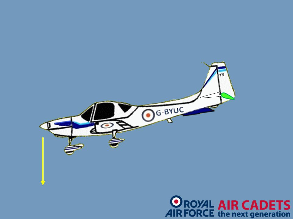
To create yaw, the one rudder pedal is moved forwards
In this example, the right pedal is pushed forwards (the left will move backwards) Use of rudder To move the aircraft in the yawing plane, the pilot uses the rudder, which is linked to the rudder pedals in the cockpit. On most conventional aircraft the rudder is just a single control surface, which is hinged to the trailing edge of the fin, where its leverage about the centre of gravity is at its greatest. The pilot’s feet rest on the rudder pedals during normal flight. To yaw to the left, the pilot pushes the left pedal forward, which makes the rudder move out to the left. The rudder is now out of alignment with the fin and at an angle of attack to the airflow. This produces a sideways force to the right, through the rudder hinge onto the tail. The tail is pushed sideways to the right, and the nose, of course to the left: the aircraft is now yawing to the left about its normal axis. The yawing ceases when the pilot centralises the rudder pedal so that the rudder again lies in line with the fin. Yaw to the right is obtained by pushing the right rudder pedal forward. As with other control movements, always remember that the aircraft will yaw whatever its initial attitude may be. Left rudder = yaw to the left Right rudder = yaw to the right The rudder moves to the right
 Use of rudder. To move the aircraft in the yawing plane, the pilot uses the rudder, which is linked to the rudder pedals in the cockpit. On most conventional aircraft the rudder is just a single control surface, which is hinged to the trailing edge of the fin, where its leverage about the centre of gravity is at its greatest. The pilot’s feet rest on the rudder pedals during normal flight. To yaw to the left, the pilot pushes the left pedal forward, which makes the rudder move out to the left. The rudder is now out of alignment with the fin and at an angle of attack to the airflow. This produces a. sideways force to the right, through the rudder hinge onto the tail. The tail is pushed sideways to the right, and the nose, of course to the left: the aircraft is now yawing to the left about its normal axis. The yawing ceases when the pilot centralises the rudder pedal so that the rudder again lies in line with the fin. Yaw to the right is obtained by pushing the right rudder pedal forward. As with other control movements, always remember that the aircraft will yaw whatever its initial attitude may be. Left rudder = yaw to the left. Right rudder = yaw to the right. The rudder moves. to the right.")
24
The aircraft yaws to the right
about the normal axis

26
The aircraft yaws to the right and continues to do
so until the rudder pedals are set back to the neutral position

28
Directional stability
CG, Stabilising, destabilising, moment arm Keel ahead/behind CG destabilising and stabilising respectively Now on slide fin is at AOA therefore lift is generated. What about the CofP ahead of the CG??? What about fin?

29
Lift Flight path Stabilising Influence of the fin: Value of lift
Moment arm CG Lift Flight path DIRECTIONAL STABILITY CG, Stabilising, destabilising, moment arm Keel ahead/behind CG destabilising and stabilising respectively Now on slide fin is at AOA therefore lift is generated. What about the CP ahead of the CG? What about fin? Enhancement features: Something causes the aircraft to yaw A large fin and/or a long moment arm

30
An aft CG requires a large fin
CG considerations So the design of the fin is critical, ie rear CG = large fin An aft CG requires a large fin

31
Longitudinal stability
longitudinal static stability the tailplane contribution must overcome the unstable wing Therefore, start with the assumption that CG and CP are coincident For simplicity assume stick fixed ie elevators locked

32
To explain this stability, we assume that the CP and CG are coincident
Lift Flight path Weight LONGITUDINAL STABILITY Longitudinal static stability the tailplane contribution must overcome the unstable wing Therefore, start with the assumption that CG and CP are coincident For simplicity assume stick fixed ie elevators locked To explain this stability, we assume that the CP and CG are coincident

33
Something causes the nose to rise
Lift Lift Flight path Weight LONGITUDINAL STABILITY longitudinal static stability the tailplane contribution must overcome the unstable wing Therefore, start with the assumption that C.G and Cp are coincident For simplicity assume stick fixed ie elevators locked Something causes the nose to rise Stabilising influence of tailplane: Area x Moment Arm = Tail Volume Lift wings - destabilising Lift tailplane - stabilising

34
Lateral stability LATERAL STABILITY

35
Lift Lift Resultant sideslip Weight
Big Fin / Diehedral / Anhedral Sweepback Wing Fuselage Interference

36
The aircraft sideslips in this direction Heading
All design features for lateral stability rely on the fact that bank results in sideslip

37
Lateral stability methods
1. Large fin of high aspect ratio (a big tall fin) Lift from fin rolls the wings level
 Lift from fin rolls the wings level.")
38
This gives more lift and tends to roll wings level
2. Dihedral Due to new direction of relative airflow the lower wing has higher AoA than the upper This gives more lift and tends to roll wings level Lift Use 90 degree sideslip to show dihedral effect However sideslip occurs Wings at different AOA ie lower has greater AOA What about anhedral and lateral stability?

39
Lateral stability methods
1. High fin 2. Dihedral 3. Sweepback 4. High mounted wing Too much lateral stability (high wing and sweepback) is very undesirable in fighter aircraft Wings are therefore anhedral to reduce the excess lateral stability Summary of Lateral Stability Methods
 is very undesirable in fighter aircraft. Wings are therefore anhedral to reduce the. excess lateral stability. Summary of Lateral Stability Methods.")
40
Any questions?

41
Questions for you …..

42
1. What are the three planes of an aircraft’s movement?
a. Pitching, lateral and rolling b. Pitching, rolling and yawing c. Yawing, longitudinal and rolling d. Longitudinal, lateral and normal

43
2. Which one of the following will REDUCE lateral stability?
a. Dihedral b. A large fin c. Sweepback d. Anhedral

44
3. What are the three axes about which an aircraft can move?
a. Pitching, lateral and longitudinal b. Pitching, rolling and yawing c. Yawing, longitudinal and normal d. Longitudinal, lateral and normal

45
4. Which three terms describe static stability?
a. Stable, neutral and unstable b. Stable, rolling and unstable c. Yawing, neutral and stable d. Neutral, unstable and pitching

Similar presentations