Download presentation
Presentation is loading. Please wait.

1
Non traditional Machining
ME635B

2
Other names Advanced manufacturing processes
Nonconventional machining processes Advanced methods of machining Non conventional methods of material removal Just by name of the processes

3
Introduction Manufacturing processes can be broadly divided into two groups primary manufacturing processes and secondary manufacturing processes. The former ones provide basic shape and size to the material as per designer’s requirement. Casting, forming, powder metallurgy are such processes to name a few. Secondary manufacturing processes provide the final shape and size with tighter control on dimension, surface characteristics etc. Material removal processes are mainly the secondary manufacturing processes

4
Difficult internal parts made by NTM

5
Conventional vs non conventional machining processes
Examples of conventional machining processes are turning, boring, milling, shaping, broaching, slotting, grinding etc Example of Non Traditional Machining (NTM) Processes Abrasive Jet Machining (AJM), Ultrasonic Machining (USM), Water Jet and Abrasive Water Jet Machining (WJM and AWJM), Electro-discharge Machining (EDM)
 Processes. Abrasive Jet Machining (AJM), Ultrasonic Machining (USM), Water Jet and Abrasive Water Jet Machining (WJM and AWJM), Electro-discharge Machining (EDM)")
6
Characteristics of conventional machining processes
mostly remove material in the form of chips by applying forces on the work material with a wedge shaped cutting tool that is harder than the work material under machining condition. Such forces induce plastic deformation within the work piece leading to shear deformation along the shear plane and chip formation Shear plane chip tool Work piece

7
Thus the major characteristics of conventional machining are:
• Generally macroscopic chip formation by shear deformation • Material removal takes place due to application of cutting forces – energy domain can be classified as mechanical • Cutting tool is harder than work piece at room temperature as well as under machining conditions

8
Non Traditional Machining (NTM) Processes on the other hand are characterised as follows:
Material removal may occur with chip formation or even no chip formation may take place. For example in AJM, chips are of microscopic size and in case of Electrochemical machining material removal occurs due to electrochemical dissolution at atomic level In NTM, there may not be a physical tool present. For example in laser jet machining, machining is carried out by laser beam. However in Electrochemical Machining there is a physical tool that is very much required for machining In NTM, the tool need not be harder than the work piece material. For example, in EDM, copper is used as the tool material to machine hardened steels. Mostly NTM processes do not necessarily use mechanical energy to provide material removal. They use different energy domains to provide machining. For example, in USM, AJM, WJM mechanical energy is used to machine material, whereas in ECM electrochemical dissolution constitutes material removal

9
The following examples are provided where NTM processes are preferred over the conventional machining process Intricate shaped blind hole – e.g. square hole of 15 mmx15 mm with a depth of 30 mm Difficult to machine material – e.g. same example as above in Inconel, Ti-alloys or carbides. Low Stress Grinding – Electrochemical Grinding is preferred as compared to conventional grinding Deep hole with small hole diameter – e.g. φ 1.5 mm hole with l/d = 20 Machining of composites.

10
classification of NTM processes is carried out depending on the nature of energy used for material removal. The broad classification is given as follows: • Mechanical Processes ⎯ Abrasive Jet Machining (AJM) ⎯ Ultrasonic Machining (USM) ⎯ Water Jet Machining (WJM) ⎯ Abrasive Water Jet Machining (AWJM) • Electrochemical Processes ⎯ Electrochemical Machining (ECM) ⎯ Electro Chemical Grinding (ECG) ⎯ Electro Jet Drilling (EJD) • Electro-Thermal Processes ⎯ Electro-discharge machining (EDM) Laser Jet Machining (LJM) ⎯ Electron Beam Machining (EBM) • Chemical Processes ⎯ Chemical Milling (CHM) ⎯ Photochemical Milling (PCM) etc.
 ⎯ Ultrasonic Machining (USM) ⎯ Water Jet Machining (WJM) ⎯ Abrasive Water Jet Machining (AWJM) • Electrochemical Processes. ⎯ Electrochemical Machining (ECM) ⎯ Electro Chemical Grinding (ECG) ⎯ Electro Jet Drilling (EJD) • Electro-Thermal Processes. ⎯ Electro-discharge machining (EDM) Laser Jet Machining (LJM) ⎯ Electron Beam Machining (EBM) • Chemical Processes. ⎯ Chemical Milling (CHM) ⎯ Photochemical Milling (PCM) etc.")
11
schematically depicts some of the NTM processes:
f = 20 – 25 kHz a = 10 ~ 25 μm tool tool Work piece Work piece tool tool Stand off distance Work piece Work piece

12
ULTRASONIC MACHINING PROCESS
Grouped under Mechanical group

13
Schematic of the USM process
Vibration frequency f ~ kHz Amplitude, a ~ 10 – 50 µm force horn tool Slurry of abrasive And water Work piece

14
Essential features of USM
In ultrasonic machining, a tool of desired shape vibrates at an ultrasonic frequency (19 ~ 25 kHz) with an amplitude of around 15 – 50 µm over the workpiece Generally the tool is pressed downward with a feed force, F. Between the tool and workpiece, the machining zone is flooded with hard abrasive particles generally in the form of a water based slurry. As the tool vibrates over the workpiece, the abrasive particles act as the indenters and indent both the work material and the tool.
 with an amplitude of around 15 – 50 µm over the workpiece. Generally the tool is pressed downward with a feed force, F. Between the tool and workpiece, the machining zone is flooded with hard abrasive particles generally in the form of a water based slurry. As the tool vibrates over the workpiece, the abrasive particles act as the indenters and indent both the work material and the tool.")
15
The abrasive particles, as they indent, the work material and if the work material is brittle the material is removed due to crack initiation, propagation and brittle fracture of the material. Therefore, USM is mainly used for machining brittle materials {which are poor conductors of electricity and thus cannot be processed by Electrochemical and Electro-discharge machining (ECM and ED)}.
}.")
16
Mechanism of material removal in USM
Material removal primarily occurs due to the indentation of the hard abrasive grits on the brittle work material. As the tool vibrates, it leads to indentation of the abrasive grits. During indentation, due to contact stresses, cracks would develop just below the contact site, then as indentation progresses the cracks would propagate due to increase in stress and ultimately lead to brittle fracture of the work material under each individual site between the abrasive grits and the workpiece. The tool material should be such that indentation by the abrasive grits does not lead to brittle failure. Thus the tools are made of tough, strong and ductile materials like steel, stainless steel and other ductile metallic alloys.

17
Model of material removal in terms of parametric issues
Other than this brittle failure of the work material due to indentation some material removal may occur due to free flowing impact of the abrasives against the work material and related solid-solid impact erosion, But it is estimated to be rather insignificant. Thus, in the current model, material removal would be assumed to take place only due to impact of abrasives between tool and workpiece, followed by indentation and brittle fracture of the workpiece.

18
d 2x dw Hemispherical material removed Therefore material removed per grit particle

19
If at any moment of time, there are an average ‘n’ of grits and the tool is vibrating at a frequency ‘f’ then material removal rate can be expressed as: Variation of force with which grit strike the work piece

20
Material Removal Rate MRR
• Amplitude of vibration (a) 15 – 50 µm • Frequency of vibration (f) – 19 – 25 kHz • Feed force (F) – related to tool dimensions • Feed pressure (p) • Abrasive size – 15 µm – 150 µm • Abrasive material • Flow strength of work material • Flow strength of the tool material • Contact area of the tool – A • Volume concentration of abrasive in water slurry – C Ratio of flow strength of Work piece and tool Dg particle diameter Do bump diameter
 15 – 50 µm • Frequency of vibration (f) – 19 – 25 kHz • Feed force (F) – related to tool dimensions • Feed pressure (p) • Abrasive size – 15 µm – 150 µm • Abrasive material • Flow strength of work material • Flow strength of the tool material • Contact area of the tool – A • Volume concentration of abrasive in water slurry – C Ratio of flow strength of. Work piece and tool. Dg particle diameter. Do bump diameter.")
21
Simple model of MRR in USM
= time of contact between particle and surface

22
Model contd. MRR= Diameter of particle(d), Amplitude and Force , f, Z
h will be decided by amplitude and Force V, volume by diameter of the particle

23
the process parameters which govern the ultrasonic machining process have been identified (last equation)and the same are listed below along with material parameters • Amplitude of vibration (a) – 15 – 50 µm • Frequency of vibration (f) – 19 – 25 kHz • Feed force (F) – related to tool dimensions • Feed pressure (p) • Abrasive size – 15 µm – 150 µm • Abrasive material – Al2O3, SiC , B4C, Boronsilicarbide, Diamond • Flow strength of work material • Flow strength of the tool material • Contact area of the tool – A • Volume concentration of abrasive in water slurry – C
 – 15 – 50 µm • Frequency of vibration (f) – 19 – 25 kHz • Feed force (F) – related to tool dimensions • Feed pressure (p) • Abrasive size – 15 µm – 150 µm • Abrasive material – Al2O3, SiC , B4C, Boronsilicarbide, Diamond • Flow strength of work material • Flow strength of the tool material • Contact area of the tool – A • Volume concentration of abrasive in water slurry – C")
24
Problems 1.Glass is being machined at a MRR of 6 mm3/min by Al2O3 abrasive grits having a grit dia of 150 μm. If 100 μm grits were used, what would be the MRR? 2. For the above problem, from the initial setting the frequency is increased from 20 kHz to 25 kHz. Determine new MRR. 3. For the first problem, the feed force is increased by 50% along with a reduction in concentration by 70%. What would be the effect on MRR.

25
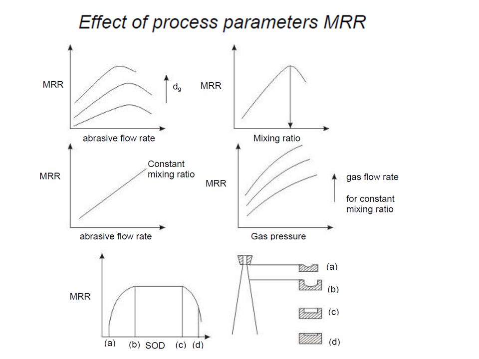
Effect of machining parameters on MRR

26
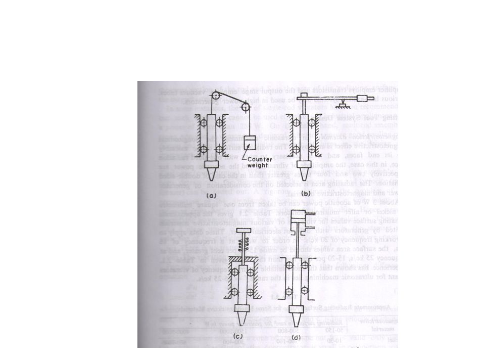
Schematic view of an Ultrasonic Machine
The typical elements of an USM are: • Slurry delivery and return system • Feed mechanism to provide a downward feed force on the tool during machining • The transducer, which generates the ultrasonic vibration • The horn or concentrator, which mechanically amplifies the vibration to the required amplitude of 15 – 50 µm and accommodates the tool at its tip

27
Working of horn as mechanical amplifier of amplitude of vibration
Magnetostrictive transducers are most popular and robust amongst all and is shown below with horn The horn or concentrator is a wave-guide, which amplifies and concentrates the vibration to the tool from the transducer. Working of horn as mechanical amplifier of amplitude of vibration The ultrasonic vibrations are produced by the transducer. The transducer is driven by suitable signal generator followed by power amplifier. The transducer for USM works on the following principle • Piezoelectric effect • Magnetostrictive effect • Electrostrictive effect

28
Different Horns used in USM
The horn or concentrator can be of different shape like • Tapered or conical • Exponential • Stepped Machining of tapered or stepped horn is much easier as compared to the exponential one

31
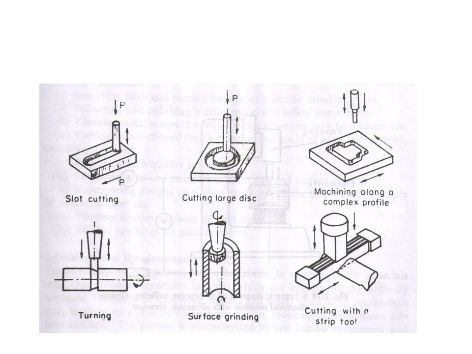
Applications of USM and Limitations of the process
• Used for machining hard and brittle metallic alloys, semiconductors, glass, ceramics, carbides etc. • Used for machining round, square, irregular shaped holes and surface impressions. • Machining, wire drawing, punching or small blanking dies. LIMITATIONS • Low MRR • Rather high tool wear • Low depth of hole

32
1. Which of the following material is not generally machined by USM
(i) Copper (ii) Glass (iii) Silicon (iv) Germanium 2. Tool in USM is generally made of (i) Glass (ii) Ceramic (iii) Carbides (iv) Steel 3. Increasing volume concentration of abrasive in slurry would affect MRR in the following manner (i) increase MRR (ii) decrease MRR (iii) would not change MRR (iv) initially decrease and then increase MRR 4. USM can be classified as the following type of non-traditional machining process (i) electrical (ii) optical (iii) mechanical (iv) chemical
 Copper. (ii) Glass. (iii) Silicon. (iv) Germanium. 2. Tool in USM is generally made of. (i) Glass. (ii) Ceramic. (iii) Carbides. (iv) Steel. 3. Increasing volume concentration of abrasive in slurry would affect MRR in the following manner. (i) increase MRR. (ii) decrease MRR. (iii) would not change MRR. (iv) initially decrease and then increase MRR. 4. USM can be classified as the following type of non-traditional machining process. (i) electrical. (ii) optical. (iii) mechanical. (iv) chemical.")
33
Abrasive Jet Machining
Domain Mechanical

34
AJM process basics In Abrasive Jet Machining (AJM), abrasive particles are made to impinge on the work material at a high velocity The jet of abrasive particles is carried by carrier gas or air The high velocity stream of abrasive is generated by converting the pressure energy of the carrier gas or air to its kinetic energy and hence high velocity jet The nozzle directs the abrasive jet in a controlled manner onto the work material, so that the distance between the nozzle and the work piece and the impingement angle can be set desirably The high velocity abrasive particles remove the material by micro-cutting action as well as brittle fracture of the work material.

35
Schematic representation of AJM

36
Different components of AJM process
In AJM, generally, the abrasive particles used are around 50 μm grit size The particles impinge on the work material at velocity of 200 m/s The nozzle has I.D. of 0.5 mm stand off distance is around 2 mm Typically under above conditions the kinetic energy of the abrasive particles would be sufficient to provide material removal due to brittle fracture of the work piece or even micro cutting by the abrasives.

37
AJM set-up To regulate the pressure To remove moisture
Eco friendly chamber To remove moisture To control particle size Air pressure around 5 bar Gases like CO2, N2 can also be used

38
Process Parameters and Machining Characteristics
The process parameters are listed below: • Abrasive ⎯ Material – Al2O3 / SiC / glass beads ⎯ Shape – irregular / spherical ⎯ Size – 10 ~ 50 μm ⎯ Mass flow rate – 2 ~ 20 gm/min • Carrier gas ⎯ Composition – Air, CO2, N2 ⎯ Density – Air ~ 1.3 kg/m3 ⎯ Velocity – 500 ~ 700 m/s ⎯ Pressure – 2 ~ 10 bar ⎯ Flow rate – 5 ~ 30 lpm

39
Process Parameters and Machining Characteristics contd.
• Abrasive Jet ⎯ Velocity – 100 ~ 300 m/s ⎯ Mixing ratio – mass flow ratio of abrasive to gas ⎯ Stand-off distance – 0.5 ~ 5 mm ⎯ Impingement Angle – 600 ~ 900 • Nozzle ⎯ Material – WC / sapphire ⎯ Diameter – (Internal) 0.2 ~ 0.8 mm ⎯ Life – 10 ~ 300 hours If the nozzle gets worn out the accuracy and MRR would be effected
 0.2 ~ 0.8 mm. ⎯ Life – 10 ~ 300 hours. If the nozzle gets worn out the accuracy and MRR would be effected.")
40
Types of abrasives used in AJM
Abrasives used for cutting : SiC, Alumina Sodium bicarbonate is used for cleaning, deburring and polishing Abrasives should have sharp edges for better cutting action Abrasives should be fine enough to mix with the gas medium Abrasives should have good flow characteristics Normally abrasives should not be reused if high MRR is desired as their cutting efficiency comes down.

41
Abrasive grain characteristics
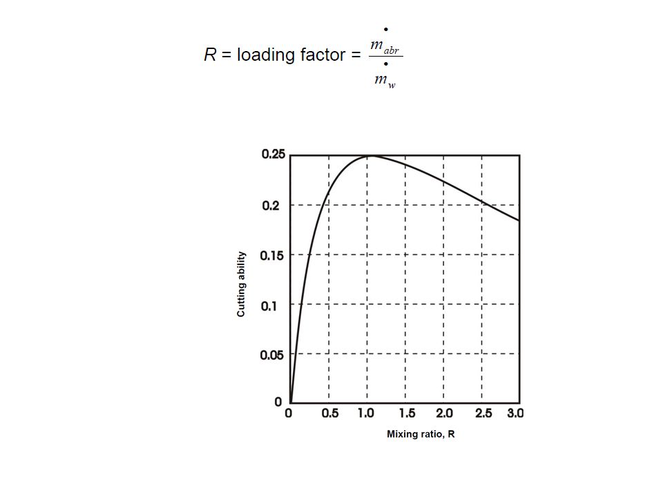
Coarse grains have better cutting ability Finer grains tend to stick together and because of less irregularity in shape has less cutting ability. However fine grains are suitable for polishing Mean number of abrasive grains per unit volume of the carrier gas is obtained as: M= Volume of flow rate of abrasive per unit time/volume of flow rate of carrier gas per unit time A large M would result in higher metal removal rate, however higher M would effect the jet velocity

42
The important machining characteristics in AJM
• The material removal rate (MRR) mm3/min or gm/min • The machining accuracy • The life of the nozzle
 mm3/min or gm/min. • The machining accuracy. • The life of the nozzle.")
44
Modelling of material removal
As mentioned earlier, material removal in AJM takes place due to brittle fracture of the work material due to impact of high velocity abrasive particles. Modelling has been done with the following assumptions: (i) Abrasives are spherical in shape and rigid. The particles are characterised by the mean grit diameter (ii) The kinetic energy of the abrasives are fully utilised in removing material (iii) Brittle materials are considered to fail due to brittle fracture and the fracture volume is considered to be hemispherical with diameter equal to chordal length of the indentation (iv) For ductile material, removal volume is assumed to be equal to the indentation volume due to particulate impact
 Abrasives are spherical in shape and rigid. The particles are characterised by the mean grit diameter. (ii) The kinetic energy of the abrasives are fully utilised in removing material. (iii) Brittle materials are considered to fail due to brittle fracture and the fracture volume is considered to be hemispherical with diameter equal to chordal length of the indentation. (iv) For ductile material, removal volume is assumed to be equal to the indentation volume due to particulate impact.")
45
Interaction of abrasive particle and the work material

46
H= hardness or flow strength of
work material Ma= number pf particles hittingx mass of each particle

47
Applications • For drilling holes of intricate shapes in hard and brittle materials • For machining fragile, brittle and heat sensitive materials • AJM can be used for drilling, cutting, deburring, cleaning and etching. • Micro-machining of brittle materials

48
Limitations • MRR is rather low (around ~ 15 mm3/min for machining glass) • Abrasive particles tend to get embedded particularly if the work material is ductile • Tapering occurs due to flaring of the jet • Environmental load is rather high.

49
Water jet machining

50
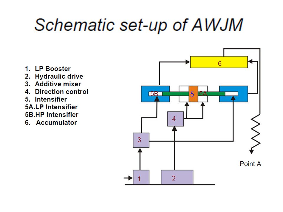
Principles Water is pumped at a sufficiently high pressure, MPa ( bar) using intensifier technology. An intensifier works on the simple principle of pressure amplification using hydraulic cylinders of different cross-sections as used in “Jute Bell Presses”. When water at such pressure is issued through a suitable orifice (generally of mm dia), the potential energy of water is converted into kinetic energy, yielding a high velocity jet (1000 m/s). Such high velocity water jet can machine thin sheets/foils of aluminium, leather, textile, frozen food etc. In pure WJM, commercially pure water (tap
 using intensifier technology. An intensifier works on the simple principle of pressure amplification using hydraulic cylinders of different cross-sections as used in Jute Bell Presses . When water at such pressure is issued through a suitable orifice (generally of mm dia), the potential energy of water is converted into kinetic energy, yielding a high velocity jet (1000 m/s). Such high velocity water jet can machine thin sheets/foils of aluminium, leather, textile, frozen food etc. In pure WJM, commercially pure water (tap.")
51
Principle contd. The potential or pressure head of the water is converted into velocity head by allowing the high-pressure water to issue through an orifice of small diameter (0.2 – 0.4 mm). The velocity of the water jet thus formed can be estimated, assuming no losses as vwj = (2pw / ρw)1/2 using Bernoulli’s equation where, pw is the water pressure and ρw is the density of water.
. The velocity of the water jet thus formed can be estimated, assuming no losses as vwj = (2pw / ρw)1/2 using Bernoulli’s equation where, pw is the water pressure and ρw is the density of water.")
52
Water jet and abrasive water jet issues
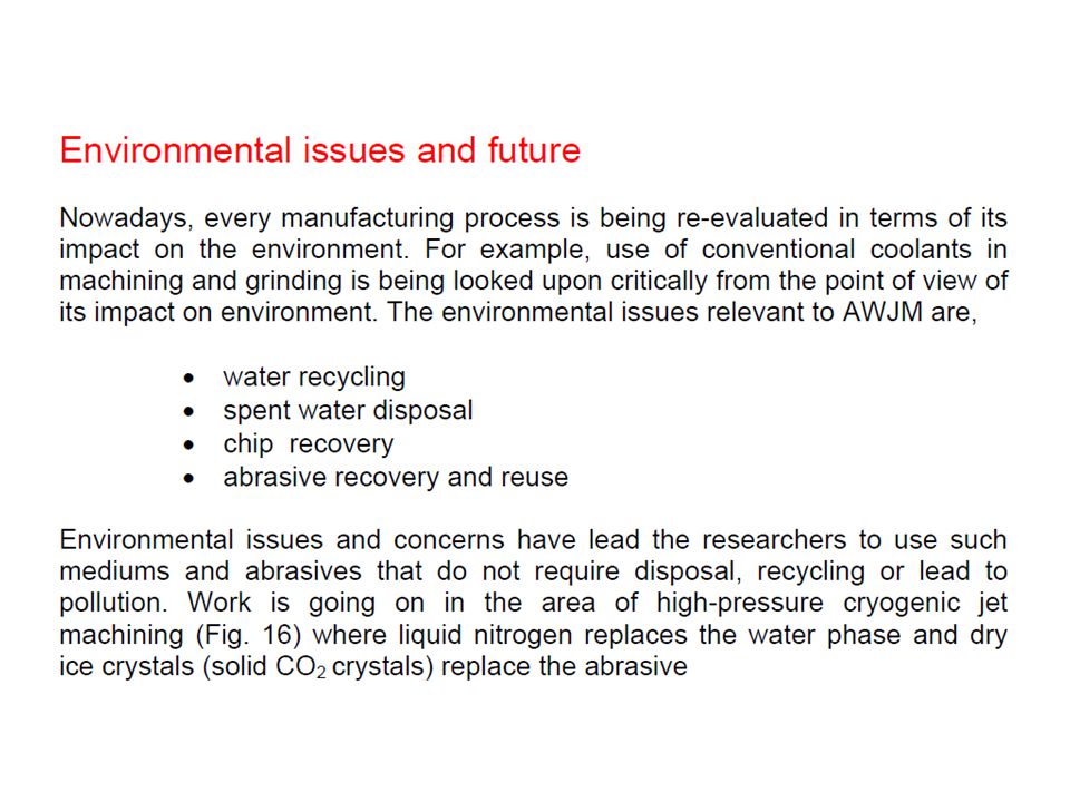
In pure WJM, commercially pure water (tap water) is used for machining purpose. However as the high velocity water jet is discharged from the orifice, the jet tends to entrain atmospheric air and flares out decreasing its cutting ability. Hence, quite often stabilisers (long chain polymers) that hinder the fragmentation of water jet are added to the water. In AWJM, abrasive particles like sand (SiO2), glass beads are added to the water jet to enhance its cutting ability by many folds.
 is used for machining purpose. However as the high velocity water jet is discharged from the orifice, the jet tends to entrain atmospheric air and flares out decreasing its cutting ability. Hence, quite often stabilisers (long chain polymers) that hinder the fragmentation of water jet are added to the water. In AWJM, abrasive particles like sand (SiO2), glass beads are added to the water jet to enhance its cutting ability by many folds.")
54
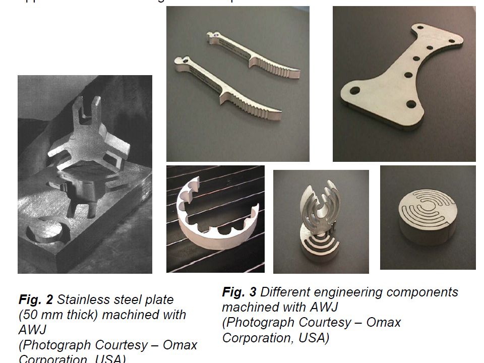
Applicants and materials generally machined by WJ and AWJ machining

57
In WJM this high velocity water jet is used for the required application where as in AWJM it is directed into the mixing chamber. The mixing chamber has a typical dimension of inner diameter 6 mm and a length of 10 mm. As the high velocity water is issued from the orifice into the mixing chamber, low pressure (vacuum) is created within the mixing chamber. Metered abrasive particles are introduced into the mixing chamber through a port. The abrasive particles are metered using different techniques like vibratory feeder or toothed belt feeder.

58
Mixing means gradual entrainment of abrasive particles within the water jet and finally the abrasive water jet comes out of the focussing tube nozzle. Schematic of mixing process

59
The orifices are typically made of sapphire
The orifices are typically made of sapphire. In commercial machines, the life of the sapphire orifice is typically around 100 – 150 hours.

64
Question 1 Question 2

65
Ans. 1 Ans. 2

66
Electro Chemical Machining
Electrochemical Machining (ECM) is a non-traditional machining (NTM) process belonging to Electrochemical category. ECM is opposite of electrochemical or galvanic coating or deposition process. Thus ECM can be thought of a controlled anodic dissolution at atomic level of the work piece that is electrically conductive by a shaped tool due to flow of high current at relatively low potential difference through an electrolyte which is quite often water based neutral salt solution.
 is a non-traditional machining (NTM) process belonging to Electrochemical category. ECM is opposite of electrochemical or galvanic coating or deposition process. Thus ECM can be thought of a controlled anodic dissolution at atomic level of the work piece that is electrically conductive by a shaped tool due to flow of high current at relatively low potential difference through an electrolyte which is quite often water based neutral salt solution.")
67
Schematic principle of Electro Chemical Machining (ECM)
Initial stage of ECM Steady state of ECM

68
During ECM, there will be reactions occurring at the electrodes i. e
During ECM, there will be reactions occurring at the electrodes i.e. at the anode or workpiece and at the cathode or the tool along with within the electrolyte.

69
Similarly, the iron atoms will come out of the anode (work piece) as:
Let us take an example of machining of low carbon steel which is primarily a ferrous alloy mainly containing iron. For electrochemical machining of steel, generally a neutral salt solution of sodium chloride (NaCl) is taken as the electrolyte. The electrolyte and water undergoes ionic dissociation as shown below as potential difference is applied NaCl ↔ Na+ + Cl- H2O H↔+ + (OH)- As the potential difference is applied between the work piece (anode) and the tool (cathode), the positive ions move towards the tool and negative ions move towards the workpiece. Thus the hydrogen ions will take away electrons from the cathode (tool) and from hydrogen gas as: 2H+ + 2e- = H2↑ at cathode Similarly, the iron atoms will come out of the anode (work piece) as: Fe = Fe e- Within the electrolyte iron ions would combine with chloride ions to form iron chloride and similarly sodium ions would combine with hydroxyl ions to form sodium hydroxide Na+ + OH- = NaOH In practice FeCl2 and Fe(OH)2 would form and get precipitated in the form of sludge. In this manner it can be noted that the work piece gets gradually machined and gets precipitated as the sludge. Moreover there is not coating on the tool, only hydrogen gas evolves at the tool or cathode.
 is taken as the electrolyte. The electrolyte and water undergoes ionic dissociation as shown below as potential difference is applied. NaCl ↔ Na+ + Cl- H2O H↔+ + (OH)- As the potential difference is applied between the work piece (anode) and the tool (cathode), the positive ions move towards the tool and negative ions move towards the workpiece. Thus the hydrogen ions will take away electrons from the cathode (tool) and from hydrogen gas as: 2H+ + 2e- = H2↑ at cathode. Similarly, the iron atoms will come out of the anode (work piece) as: Fe = Fe e- Within the electrolyte iron ions would combine with chloride ions to form iron chloride and similarly sodium ions would combine with hydroxyl ions to form sodium hydroxide. Na+ + OH- = NaOH. In practice FeCl2 and Fe(OH)2 would form and get precipitated in the form of sludge. In this manner it can be noted that the work piece gets gradually machined and gets precipitated as the sludge. Moreover there is not coating on the tool, only hydrogen gas evolves at the tool or cathode.")
70
Schematic representation of electro-chemical reactions

71
The voltage is required to be applied for the electrochemical reaction to proceed at a steady state. That voltage or potential difference is around 2 to 30 V. The applied potential difference, however, also overcomes the following resistances or potential drops. They are: • The electrode potential • The activation over potential • Ohmic potential drop • Concentration over potential • Ohmic resistance of electrolyte

72
Applications ECM technique removes material by atomic level dissolution of the same by electrochemical action. Thus the material removal rate or machining is not dependent on the mechanical or physical properties of the work material. It only depends on the atomic weight and valency of the work material and the condition that it should be electrically conductive. Thus ECM can machine any electrically conductive work material irrespective of their hardness, strength or even thermal properties. Moreover as ECM leads to atomic level dissolution, the surface finish is excellent with almost stress free machined surface and without any thermal damage.

73
Applications ECM is used for • Die sinking • Profiling and contouring
• Trepanning •Grinding • Drilling • Micro-machining

74
The electrochemical machining system has the following modules: 1
The electrochemical machining system has the following modules: 1.Power supply 2.Electrolyte filtration and delivery system 3.Tool feed system 4.Working tank Schematic diagram of an electrochemical drilling unit

75
Different applications of Electro Chemical Machining

76
Drilling and Trepanning by ECM

Similar presentations


. 2 Electrochemical Machining Nontraditional machining process of removing metal from extremely hard materials using.>")


>")


, EDM Grinding( 연삭 ), EDM( 방전 ) Associate Professor Su-Jin KimSu-Jin Kim School.>")


 B.Sc (ENGINEERING) LEVEL 2 (Semester 2)>")
Shantanu Bhattacharya, ME, IITK, (2)Prof.>")
Shantanu Bhattacharya, ME, IITK, (2)Prof.>")


