Download presentation
Presentation is loading. Please wait.

1
EE4503 Electrical Systems Design
Branch circuit and Feeder (Motor)
")
2
Topics Motor Branch Circuit Protection & Controller Feeder

3
Motor Branch Circuit

4
Motor Branch Circuit Motor Branch Circuit Conductors
Motor Branch Circuit Short Circuit Protection Overload Protection Motor Controller Motor Disconnect Motor Control Circuits

5
Motor Branch Circuit Conductor Disconnect Short Circuit Protection
Overload Protection Controller & Control Circuit

6
Motor Branch Circuit Type of Motor
Induction Motor 1 phase and 3 phase Synchronous Motor (only 3 phase) Armature & Field (DC) DC Motor Armature & Field
 Armature & Field (DC) DC Motor. Armature & Field.")
7
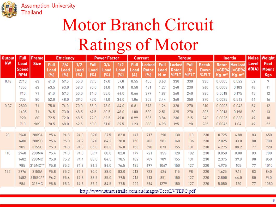
Motor Branch Circuit Ratings of Motor
Power: HP or kW # of phase Voltage Current ( 𝑃𝑜𝑤𝑒𝑟 𝑉𝑜𝑙𝑡𝑎𝑔𝑒 /𝐸𝑓𝑓𝑖𝑐𝑖𝑒𝑛𝑐𝑦) Check Manufacturer for Data
 Check Manufacturer for Data.")
8
Motor Branch Circuit Ratings of Motor
9
Motor Branch Circuit Current (cable) Calculation
Normal Operation: 𝐼 𝑐 ≥1.25 𝐼 𝑛 Multi-speed Motor: maximum current On-Off Operation: 𝐼 𝑐 ≥ 𝐾 1 𝐼 𝑛 when 𝐾 1 is the multiplier

10
Motor Branch Circuit Current (CB) Calculation
Motor Type Fuse (Fast Blown) (Slow Blown) CB (instantaneous) (invert time) Induction (DOL) 3.0 1.75 7.0 2.5 Induction (Auto Transformer) 2.0 Wound Rotor 1.5 DC
 (Slow Blown) CB. (instantaneous) (invert time) Induction (DOL) Induction (Auto Transformer) 2.0. Wound Rotor DC.")
11
Motor Branch Circuit Current Calculation
Ground Cable 115% of the rated current 𝐼 𝑝𝑒 =1.15 𝐼 𝑛

12
Short Circuit Protection
Able to handle the starting current Fuse Non Time-Delay Fuse Time-Delay Fuse Circuit Breaker Inverse Time Circuit Breaker (normal) Instantaneous Circuit Breaker
 Instantaneous Circuit Breaker.")
13
Short Circuit Protection Circuit Breaker

14
Overload Protection To protect overheat of the motor
Circuit Breaker cannot function well for overload because of the starting current Three methods of detecting temperature Bimetal Thermal Overload Relay Electronic Overload Relay Thermistor Protective Relay

15
Motor Controller Starter Inverter DOL: usually less than 7.5kW
Reduced Voltage Starter Inverter

16
Motor Controller Reduced Voltage Starter Star-Delta Starting
Autotransformer Starting Resistant Starting Part-Winding Starting Elecronics Starting

17
Motor Controller Contactor
Turn on-off the motor The rating of Contactor needs to be higher than the rating of Motor Utilization Category AC2: handle 2-5 times the nominal current AC3: handle 5-7 times, but stop at nominal AC4: handle high amount of on-off operation

18
Motor Controller Reduced Voltage Starter Star-Delta Starting
Autotransformer Starting Resistant Starting Part-Winding Starting Elecronics Starting

19
Motor Controller components
Power Circuit Usually 3 phase power circuit Control Circuit Single phase or DC circuit

20
Motor Controller Direct On Line Starting

21
Motor Controller Star-Delta Starting

22
Disconnecting Means Disconnect when circuit is live
Design for inductive load Install “within sight” and less than 15m Rating is higher than 115% of motor rating

23
Feeder Cable All motor: 𝐼 𝐹 ≥1.25 𝐼 𝑛,𝑚𝑎𝑥 + 𝐼 𝑛
Combination of Motor and other loads: 𝐼 𝐹 ≥1.25 𝐼 𝑛,𝑚𝑎𝑥 + 𝐼 𝑛 𝐼 𝐿 𝐼 𝐿 is continuous load Neutral can be a lot smaller but not smaller than Ground

24
Feeder CB All motor: 𝐼 𝐹 ≥ 𝐼 𝐶𝐵,𝑚𝑎𝑥 + 𝐼 𝑛
Combination of Motor and other loads: 𝐼 𝐹 ≥ 𝐼 𝐶𝐵,𝑚𝑎𝑥 + 𝐼 𝑛 𝐼 𝐿 𝐼 𝐿 is continuous load Neutral can be a lot smaller but not smaller than Ground

25
Reference Electrical Systems Design: ประสิทธิ์ พิทยพัฒน์
Depend on the area, end-user can connect to the “meter” of the authority in three ways.

Similar presentations


