Download presentation
Presentation is loading. Please wait.

1
EE4503 Electrical Systems Design
Branch circuit and Feeder (Lighting and Appliances)
")
2
Topics Characteristics of Loads Circuits Design Branch Circuit
Feeder Circuit Load Schedule

3
Characteristics of Loads
Continuous Load More than 3 hrs. of continuous usage e.g. lighting, air condition Non-continuous Load: Less than 3 hrs. of continuous usage e.g. electric oven, microwave When not sure, add 25% more

4
Characteristics of Loads Definition
Total Connected Load: total kVA or MVA listed Maximum Demand: the maximum kVA or MVA used at the same time

5
Characteristics of Loads Definition
Demand Factor (D.F.): ratio of “Maximum Demand” to “Total Connected Load” (𝐷.𝐹. = 𝑀𝑎𝑥𝑖𝑚𝑢𝑚 𝐷𝑒𝑚𝑎𝑛𝑑 𝑇𝑜𝑡𝑎𝑙 𝐶𝑜𝑛𝑛𝑒𝑐𝑡𝑒𝑑 𝐿𝑜𝑎𝑑 ∗100%) Diversity Factor: summation of every branched circuits’ maximum demand to the system’s maximum demand (always greater than or equal to 1.0) Diversity Factor: (Dormitory Maximum Demand + Classroom Maximum Demand)/Maximum Demand
: ratio of Maximum Demand to Total Connected Load (𝐷.𝐹. = 𝑀𝑎𝑥𝑖𝑚𝑢𝑚 𝐷𝑒𝑚𝑎𝑛𝑑 𝑇𝑜𝑡𝑎𝑙 𝐶𝑜𝑛𝑛𝑒𝑐𝑡𝑒𝑑 𝐿𝑜𝑎𝑑 ∗100%) Diversity Factor: summation of every branched circuits’ maximum demand to the system’s maximum demand (always greater than or equal to 1.0) Diversity Factor: (Dormitory Maximum Demand + Classroom Maximum Demand)/Maximum Demand.")
6
Characteristics of Loads Definition
Peak Load (P): the maximum kVA or MVA at the given periond (e.g. 15 min) Load Factor (L.F.): ratio of “Average Load” to the “Peak Load” (𝐿.𝐹. = 𝐸 𝑃∗𝑇 ∗100%). 𝐸 is total energy for period of time 𝑇 Diversity Factor: (Dormitory Maximum Demand + Classroom Maximum Demand)/Maximum Demand
: the maximum kVA or MVA at the given periond (e.g. 15 min) Load Factor (L.F.): ratio of Average Load to the Peak Load (𝐿.𝐹. = 𝐸 𝑃∗𝑇 ∗100%). 𝐸 is total energy for period of time 𝑇. Diversity Factor: (Dormitory Maximum Demand + Classroom Maximum Demand)/Maximum Demand.")
7
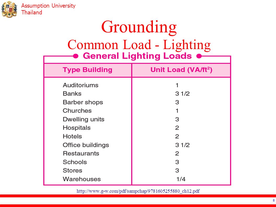
Characteristics of Loads Common Load
Lighting: about 20-50% of total load or VA/m2 Receptacle: if no specific information, VA/set (1, 2 or 3 outlets) HVAC: 1TR (12,000 BTU) is about kVA Motor Escalator: manufacturer’s specification
 HVAC: 1TR (12,000 BTU) is about kVA. Motor. Escalator: manufacturer’s specification.")
8
Grounding Common Load - Lighting
9
Grounding Common Load - Escalator

10
Circuit Design Branch Circuit Feeder Circuit Main Circuit

11
Branch Circuit Connect from a distribution panel to load or receptacle
Lighting or Appliance Branch Circuit Lighting Branch Circuit Receptacle Branch Circuit Lighting & Receptacle Branch Circuit Individual Branch Circuit

12
Branch Circuit Calculation
Load of a branch circuit (BC) at least the total load connected to that branch. Conductor Sizing Current Rating of CB Current Rating of CB Maximum Load Size of a BC goes by the current rating of CB: 15(16)A, 20A, 25A, 30(32)A, 40A, 50A, 63A
 at least the total load connected to that branch. Conductor Sizing Current Rating of CB. Current Rating of CB Maximum Load. Size of a BC goes by the current rating of CB: 15(16)A, 20A, 25A, 30(32)A, 40A, 50A, 63A.")
13
Branch Circuit Design Procedure
Find “Load” Calculate “Circuit Breaker” (% of BC) Calculate “Cable” Verify “Voltage Drop”: 1-2% of rated voltage 𝑉 𝑑 =2∗𝐼∗𝑙∗ 𝑅 cos 𝜃 +𝑋 sin 𝜃 ?? safety factor ??
 Calculate Cable Verify Voltage Drop : 1-2% of rated voltage. 𝑉 𝑑 =2∗𝐼∗𝑙∗ 𝑅 cos 𝜃 +𝑋 sin 𝜃. safety factor")
14
Branch Circuit Design Recommendations
Lighting Circuit: continuous load 50-70% of BC (no more than 80%) or allowance of 10-30% Individual Branch Circuit: load is known Should be no more than 80% of BC
 or allowance of 10-30% Individual Branch Circuit: load is known. Should be no more than 80% of BC.")
15
Branch Circuit Design Recommendations
Receptacles Circuit: single, duplex, triplex 180VA per set (200VA for ease) Individual Circuit with ELCB: heater, Jacuzzi Receptacles Circuit with ELCB: toilet, kitchen, basement, outdoor, < 1.5m from water ?? Some recommendations can be relaxed ??
 Individual Circuit with ELCB: heater, Jacuzzi. Receptacles Circuit with ELCB: toilet, kitchen, basement, outdoor, < 1.5m from water. Some recommendations can be relaxed")
16
Branch Circuit Design Recommendations
Separate the type of load: lighting on one BC Future Load: 20% spare at least 40% if continuous load Cable size is no smaller than 2.5mm2 BC for receptacles contains less than 10 sets

17
Branch Circuit Drawing
# of hash marks is # of cables No hash mark means 2 cables One hash mark + number is the number of cables Arrow + Lx is connected to circuit breaker (phase) #x
 #x.")
18
Branch Circuit Panelboard
No more than 42 circuit No longer than 50 m Easy to access (no higher than 1.8m) Rated is more than the rated of the cable At least one panel board per floor Must have protection equipment (CB)
 Rated is more than the rated of the cable. At least one panel board per floor. Must have protection equipment (CB)")
19
Branch Circuit Panelboard
Should be in the center: balance the voltage drop Should be close to the incoming: shortest feeder Three types Active Branch Circuit (60-80%) Spare Branch Circuit with CB (10-20%) Spare Branch Circuit (10-20%)
 Spare Branch Circuit with CB (10-20%) Spare Branch Circuit (10-20%)")
20
Branch Circuit Feeder Rated current of feeder is the total load deducted by the “demand factor” Feeder Cable Rating of CB Rating of CB Feeder’s Rated Current

21
Branch Circuit Feeder – Demand Factor
Demand Factor is the ratio of the maximum usage power at any certain time to the total connected load. There are tables for the demand factor, e.g. receptacles in kitchen, lighting. If not specify, 0.8 is a good number

22
Branch Circuit Feeder – Neutral
In single phase system, neutral cable will be the same size and line cable. In three phase, neutral cable can be reduced. Less than 200A, use the phase current More than 300A Without Harmonics, 𝐼 𝑛 = ∗( 𝐼 𝑝 −200) With Harmonics, use the phase current
 With Harmonics, use the phase current.")
23
Branch Circuit Feeder - Design Procedure
Sum up total BCs’ load Calculate “Circuit Breaker” Calculate “Cable”: Phase then Neutral Verify “Voltage Drop”: 1-2% of rated voltage 𝑉 𝑑 = 3 ∗𝐼∗𝑙∗ 𝑅 cos 𝜃 +𝑋 sin 𝜃

24
Branch Circuit Load Schedule
List of connected load CB number start from 1(A), 3(B), 5(C), 2(A), 4(B), 6(C) then 7(A), 9(B), 11(C), 8(A), 10(B), 12(C) Consider the balance of load in all phases (less than 20% is recommended)
, 3(B), 5(C), 2(A), 4(B), 6(C) then 7(A), 9(B), 11(C), 8(A), 10(B), 12(C) Consider the balance of load in all phases (less than 20% is recommended)")
25
Branch Circuit Load Schedule – Design Recommendation
Load Calculation Non-continuous Load, no multiplier Continuous Load, 1.25 multiplier (or more in case of future expansion) If not sure, treat as continuous load. Then choose the circuit breaker Then choose the cable
 If not sure, treat as continuous load. Then choose the circuit breaker. Then choose the cable.")
26
Branch Circuit & Feeder Design Procedure
Make the Load Schedule Design Branch Circuit Design Feeder (from the load schedule)
")
27
Branch Circuit & Feeder Design Examples

28
Branch Circuit & Feeder Design Examples

29
Reference Electrical Systems Design: ประสิทธิ์ พิทยพัฒน์
Depend on the area, end-user can connect to the “meter” of the authority in three ways.

Similar presentations


 What is the NEC? A.National Electrical Code B.National Electrical Corporation C.A kind of cookie D.National Energy Code.>")

>")