Download presentation
Presentation is loading. Please wait.

1
EE4503 Electrical Systems Design
Grounding

2
Topics Introduction to Grounding Grounding of Electrical Systems
Grounding Systems Grounding Resistant

3
Grounding Grounding or Earthing
Make the potential difference become the same as ground/earth. For human safety and equipment safety Follow NEC Article 250

4
Grounding Category System Grounding: connect the “live” portion of the electrical system to ground, e.g. neutral Equipment Grounding: connect a part (having no current) of the equipment to ground, e.g. case live = having current
 of the equipment to ground, e.g. case. live = having current.")
5
Grounding Components Grounding Electrode (System)
Grounding Electrode Conductor Grounded Conductor Main Bonding Jumper Equipment Grounding Conductor

6
Electrical Systems Design: ประสิทธิ์ พิทยพัฒน์
Grounding Components Electrical Systems Design: ประสิทธิ์ พิทยพัฒน์

7
Grounding Components

8
Grounding Common Grounding Systems
System Grounding Service Equipment Grounding Separately Derived System Equipment Grounding Computer Grounding

9
Grounding AC System Grounding
“live” portions of the electrical system Protect Overvoltage: specially from lightning Stabilize voltage level referring to ground Be part of protection circuit: be part of the short- circuit current 50V, 50 to 1kV, more than 1kV

10
Grounding AC System Grounding – 50V
NEC Standard The source is stepped down from more than 150V is stepped down from the ungrounded system Cable in over the ground outside the building

11
Grounding AC System Grounding – 50 to 1kV
Usually at the distributed transformer Neutral is grounded

12
Grounding AC System Grounding – Electrode
Grounding Electrode Conductor Connected to three parts Grounded Conductor: usually neutral line Equipment Grounding Conductor Main Bonding Jumper

13
Grounding AC System Grounding – Electrode
Cable: continuous copper cable with insulator Installation: connect to a surface, recommend conduit EMC: metal component needed to be connect to ground

14
Grounding AC System Grounding – Electrode
Cable: continuous copper cable with insulator Installation: connect to a surface, conduit (recommended) EMC: metal component needed to be connect to ground Connection: Exothermic Welding, or other recommended methods
 EMC: metal component needed to be connect to ground. Connection: Exothermic Welding, or other recommended methods.")
15
Grounding AC System Grounding – Exothermic Welding

16
Grounding AC System Grounding – Cable Size

17
Grounding AC System Grounding – Cable Size
Meter (A) MCB (A) Cable Sizing (sq.mm.) Voltage (V) Incoming Cable in Air (Grounding) Incoming Cable in Conduit (Grounding) 5 (15) 1 16 4 (10) 4,10**(10) 300 15 (45) 50 10 (10) 16 (10) 30 (100) 100 25 (10) 50 (16) 50 (150) 125 35 (10) 70 (25) 3 750 200 250 95 (25) 150 (35) 400 500 240 (50) 500 (70)
 MCB (A) Cable Sizing (sq.mm.) Voltage (V) Incoming Cable in Air (Grounding) Incoming Cable in Conduit (Grounding) 5 (15) (10) 4,10**(10) (45) (10) 16 (10) 30 (100) (10) 50 (16) 50 (150) (10) 70 (25) (25) 150 (35) (50) 500 (70)")
18
Grounding Service Equipment Grounding
Usually two points of grounding: at the transformer and at the main distribution box “Main Bonding Jumper” connects the metal part of the main distribution box to ground “Main Bonding Jumper” (now) connects to the grounded conductor Same calculation as “System Grounding”
 connects to the grounded conductor. Same calculation as System Grounding")
19
Grounding Separately Derived System
Electrical systems that are separated inside the facility (after the utility): e.g. from utility and generator Common Neutral: grounded only at the main distribution box Isolated Neutral: grounded separately and have the isolated ground rod
: e.g. from utility and generator. Common Neutral: grounded only at the main distribution box. Isolated Neutral: grounded separately and have the isolated ground rod.")
20
Grounding Equipment Grounding
Grounding for the “non-live” metal portion The enclosure has the same potential level as the ground (protected for human contact) Improve short-circuit protection: conductor touching enclosure Path for the leakage current
 Improve short-circuit protection: conductor touching enclosure. Path for the leakage current.")
21
Grounding Equipment Grounding – What to be grounded?
Metal enclosure & Protected Fence: metal conduit, panelboard enclosure, electric crane, elevator’s enclosure Protected fence: HV station Electrical Appliance specially with outlet: more than 150V, except having proper insulator (e.g. double insulator)
")
22
Grounding Equipment Grounding – What to be grounded?
Fixed Equipment with hard wires specially able to be touched Close contact to human: grounded within 2.4m from ground and 1.5m from wall Electrical contact to metal Wet area

23
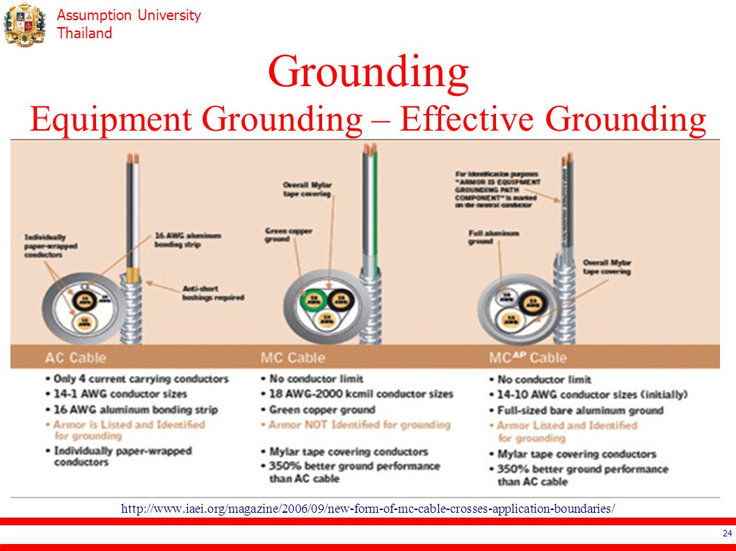
Grounding Equipment Grounding – Effective Grounding
Continuity Low Impedance High Ampacity Copper: with or without insulator Busware: that specified for grounding Metal Armor of some cables: AC, MI, MC

24
Grounding Equipment Grounding – Effective Grounding
25
Grounding Equipment Grounding – Sizing
Tables (if common ground cable, take maximum one) In general: according to rating of CB For motor: according to the rating of overload protection.
 In general: according to rating of CB. For motor: according to the rating of overload protection.")
26
Grounding Equipment Grounding – Sizing
Rated Circuit Breaker or Overload Protector (A) Ground Cable Size (mm2) 16 1.5 (recommended 2.5) 20 2.5 40 4 70 6 100 10 200 400 25 500 35 Electrical Systems Design: ประสิทธิ์ พิทยพัฒน์
 Ground Cable Size (mm2) (recommended 2.5) Electrical Systems Design: ประสิทธิ์ พิทยพัฒน์")
27
Grounding Computer Grounding
Power Distribution Grounding Single Ground Point to protect “Ground Loop” High Frequency Grounding in the order of kHz or MHz 60cm x 60cm conductor grid Recommend common ground electrode

28
Grounding Electrode System Earth
Refered as 0 Deeper in the ground (more humidity) lower resistance Good for make the reference voltage as 0 ** not capable enough to conduct high current
 lower resistance. Good for make the reference voltage as 0. ** not capable enough to conduct high current.")
29
Grounding Electrode System Electrode
Existing Electrode Underground metal pipes Building structures Pile Under ground metal structures Made Electrode Ground Rods Concrete Encased Electrode Buried Plate Ring Grid

30
Grounding Electrode System Ground Rod
Copper rod with at least 16mm in diameter and 2.4 m in length Few longer rods are better than many short rods

31
Earthing Scheme 2,3 or 4 characters
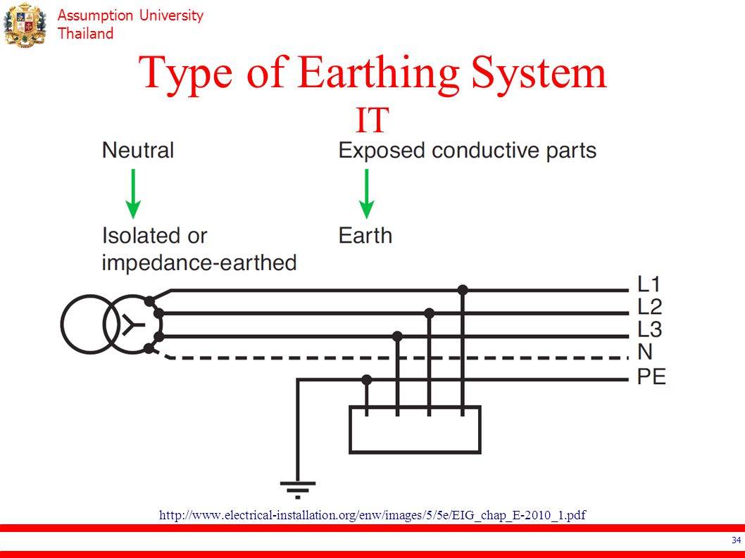
1st: relation between distribution system and earth T means single point connecting to earth I means isolated from earth

32
Earthing Scheme 2nd: relation exposed conductive part and earth
T means no connection to the electrical system N means there is a connection between the exposed conductive and electrical system (neutral)
")
33
Earthing Scheme 3rd(if any): arrangement of neutral (N) and protective conductor (PE) S means separation between N & PE C means common between N & PE

34
Type of Earthing System IT
35
Type of Earthing System TT

36
Type of Earthing System TN-C

37
Type of Earthing System TN-S

38
Type of Earthing System TN-C-S

39
Resistance to Ground By E.I.T. standard 5 Ohm
Some area, authority might allow up to 25 Ohm If cannot achieve, try adding extra electode

40
Reference Electrical Systems Design: ประสิทธิ์ พิทยพัฒน์
Depend on the area, end-user can connect to the “meter” of the authority in three ways.

Similar presentations


 Loops Stacey Mighty Malcolm Distribution.>")

 ARTI DWIVEDI (ET 4 TH SEM) DIKSHA CHANDRAKAR (ET 4 TH SEM) MAMTA CHOUDHARY.>")


