Download presentation
Presentation is loading. Please wait.

1
Lecture 5: Orbit

2
read King et al. Appendix

3
Satellite Orbits At what location is the satellite looking?
When is the satellite looking at a given location? How often is the satellite looking at a given location? At what angle is the satellite viewing a given location?

4
Altitude classifications
Low Earth orbit (LEO): Geocentric orbits ranging in altitude from 0–2000 km (0–1240 miles) Medium Earth orbit (MEO): Geocentric orbits ranging in altitude from 2000 km (1240 miles) to just below geosynchronous orbit at 35786 km (22240 miles). Also known as an intermediate circular orbit. High Earth orbit (HEO): Geocentric orbits above the altitude of geosynchronous orbit 35786 km (22240 miles).
: Geocentric orbits ranging in altitude from 0–2000 km (0–1240 miles) Medium Earth orbit (MEO): Geocentric orbits ranging in altitude from 2000 km (1240 miles) to just below geosynchronous orbit at km (22240 miles). Also known as an intermediate circular orbit. High Earth orbit (HEO): Geocentric orbits above the altitude of geosynchronous orbit km (22240 miles).")
5
the satellite’s height, eccentricity, and inclination determine the satellite’s path and what view it will have of Earth.

6
Kepler’s laws 1. Satellites follow an elliptical orbit with the Earth as one focus Foci Apogee Perigee 3rd law (law of harmonics): The square of a planet's orbital period is proportional to its mean distance from the Sun cubed. The mathematical way to describe Kepler's 3rd law is: P2 ~R3
: The square of a planet s orbital period is. proportional to its mean distance from the Sun cubed. The mathematical way. to describe Kepler s 3rd law is: P2 ~R3.")
7
Ellipse An ellipse is defined as follows: For two given points, the foci, an ellipse is the locus of points such that the sum of the distance to each focus is constant. BTW, Locus -- A word for a set of points that forms a geometric figure or graph

8
Physics for satellite

9
42 T2= r3 Gme Centripetal Force, Gravity
When a body moving in a circle, from Newton's 2nd law there must be a force acting on it to cause the acceleration. This force will also be directed toward the centre and is called the centripetal force. F1 = ma = mv2/r = mrω2 Where m is the mass of the body and v is the speed in the circular path of radius r Newton's 2nd law F2 = ma g= GM/r2 T2= r3 42 Gme

10
Period of orbit Period of orbit T2= r3 42 Gme Radius of the orbit Gravitational constant Mass of the Earth Valid only for circular orbits (but a good approximation for most satellites) Radius is measured from the center of the Earth (satellite altitude+Earth’s radius) Accurate periods of elliptical orbits can be determined with Kepler’s Equation
 Radius is measured from the center of the Earth (satellite altitude+Earth’s radius) Accurate periods of elliptical orbits can be determined with Kepler’s Equation.")
11
Definition of Orbital Period of a Satellite
The orbital period of a satellite around a planet is given by where T0 = orbital period (sec) Rp = planet radius (6380 km for Earth) H¢ = orbit altitude above planet’s surface (km) gs = acceleration due to gravity ( km s-2 for Earth)
 Rp = planet radius (6380 km for Earth) H¢ = orbit altitude above planet’s surface (km) gs = acceleration due to gravity ( km s-2 for Earth)")
12
Eccentricity Eccentricity refers to the shape of the orbit. A satellite with a low eccentricity orbit moves in a near circle around the Earth. An eccentric orbit is elliptical, with the satellite’s distance from Earth changing depending on where it is in its orbit.

13
Orbital inclination Inclination is the angle of the orbit in relation to Earth’s equator. A satellite that orbits directly above the equator has zero inclination. If a satellite orbits from the north pole (geographic, not magnetic) to the south pole, its inclination is 90 degrees.
 to the south pole, its inclination is 90 degrees.")
14
Types of orbits Sunsynchronous orbits: An orbit in which the satellite passes every location at the same time each day Noon satellites: pass over near noon and midnight Morning satellites: pass over near dawn and dusk Often referred to as “polar orbiters” because of the high latitudes they cross Usually orbit within several hundred to a few thousand km from Earth

15
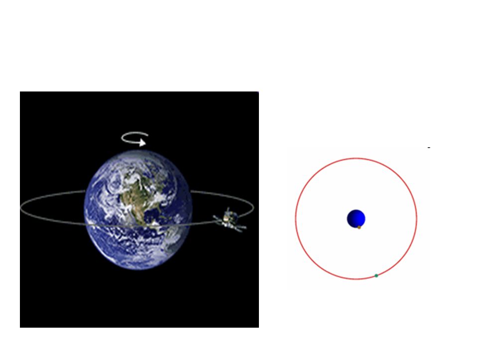
Types of orbits Geostationary (geosynchronous) orbits: An orbit which places the satellite above the same location at all times Must be orbiting approximately 36,000 km above the Earth Satellite can only “see” one hemisphere

16
Atmospheric Remote Sensing Sensors, Satellite Platforms, and Orbits
Satellite orbits and platforms Low Earth orbit Sunsynchronous and repeat coverage Precessing Geosynchronous orbit Sensor scanning modes Whiskbroom and pushbroom scanners Active and passive microwave radiometers Next lecture

17
Sun Synchronous (Near Polar)
Video Sun-Synchronous Orbit at 800km Terra orbit -

18
Low Earth Orbit Concepts
Descending node Ascending node Perigee Ground track Orbit Inclination angle Equator Orbit South Pole Apogee

19
Sun-Synchronous Polar Orbit
Earth Revolution Equatorial illumination angle Satellite Orbit Satellite orbit precesses (retrograde) 360° in one year Maintains equatorial illumination angle constant throughout the year ~10:30 AM in this example
 360° in one year. Maintains equatorial illumination angle constant throughout the year. ~10:30 AM in this example.")
20
Sun-Synchronous Orbit of Terra

21
Spacing Between Adjacent Landsat 5 or 7 Orbit Tracks at the Equator

22
Timing of Adjacent Landsat 5 or 7 Coverage Tracks
Adjacent swaths are imaged 7 days apart

23
Polar-Orbiting Satellite in Low Earth Orbit (LEO)
Example from Aqua

24
Tropical Rainfall Measuring Mission Orbit (Precessing)
A precessing low-inclination (35°), low-altitude (350 km) orbit to achieve high spatial resolution and capture the diurnal variation of tropical rainfall Raised to 402 km in August 2001 Before we can justify flying a fleet of satellites to observe rainfall from space, we must first demonstrate that we can achieve high-quality rainfall measurements from space. TRMM was meant to provide that proof-of-concept demonstration using one satellite. The necessary compromise was reduced global coverage and temporal sampling. The issue of limited sampling had, no doubt, been a factor in promoting TRMM as a climate observation program, but that was before using these observations in data assimilation. We now know that we can derive tremendous from space-based rainfall observations even with limited sampling, a point that I will return to later.
, low-altitude (350 km) orbit to achieve high spatial resolution and capture the diurnal variation of tropical rainfall. Raised to 402 km in August Before we can justify flying a fleet of satellites to observe rainfall from space, we must first demonstrate that we can achieve high-quality rainfall measurements from space. TRMM was meant to provide that proof-of-concept demonstration using one satellite. The necessary compromise was reduced global coverage and temporal sampling. The issue of limited sampling had, no doubt, been a factor in promoting TRMM as a climate observation program, but that was before using these observations in data assimilation. We now know that we can derive tremendous from space-based rainfall observations even with limited sampling, a point that I will return to later.")
25
TRMM Coverage 1 day coverage 2 day coverage
Before we can justify flying a fleet of satellites to observe rainfall from space, we must first demonstrate that we can achieve high-quality rainfall measurements from space. TRMM was meant to provide that proof-of-concept demonstration using one satellite. The necessary compromise was reduced global coverage and temporal sampling. The issue of limited sampling had, no doubt, been a factor in promoting TRMM as a climate observation program, but that was before using these observations in data assimilation. We now know that we can derive tremendous from space-based rainfall observations even with limited sampling, a point that I will return to later.

26
Orbital Characteristics of Selected Missions Low Earth Orbit & Precessing Missions

27
Sunsynchronous image (SMMR)
")
28
Sunsynchronous image (AVHRR)
")
29
Types of orbits Geostationary (geosynchronous) orbits: An orbit which places the satellite above the same location at all times Must be orbiting approximately 36,000 km above the Earth Satellite can only “see” one hemisphere

31
Video for Geo. satellite

32
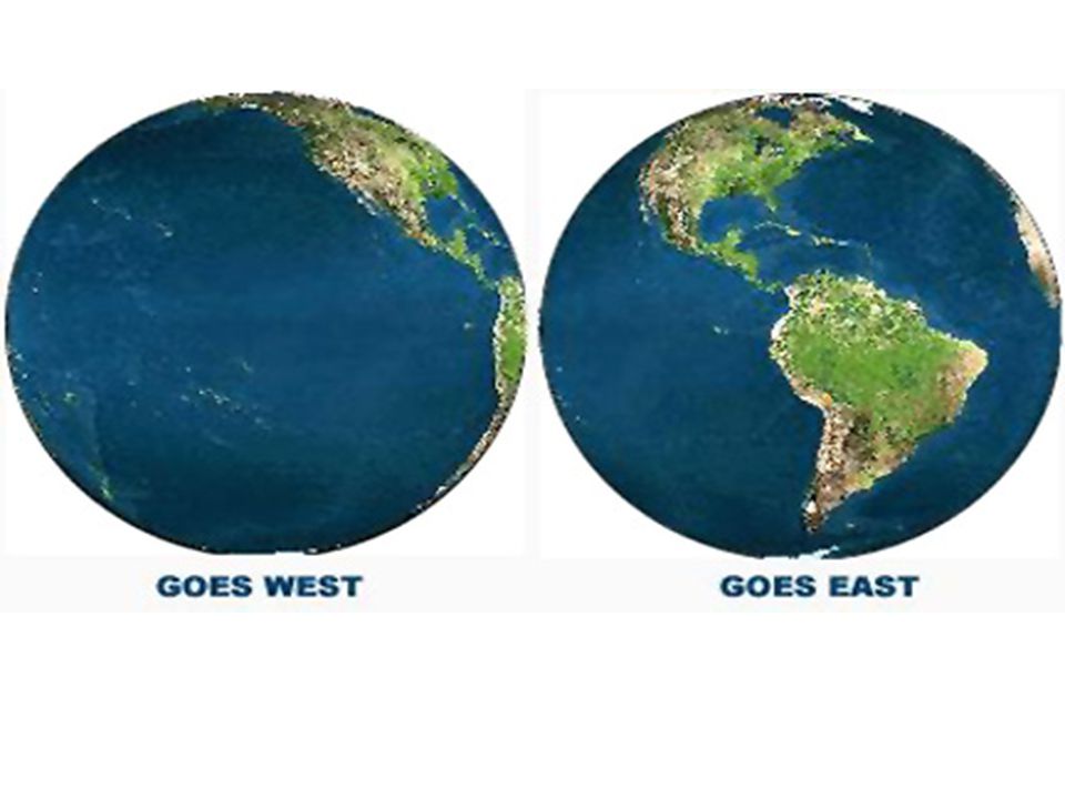
Geostationary Image (GOES-8)
")
34
Geostationary satellites
GMS (Japan) Geostationary Meteorological Satellite Located over 140ºE longitude Similar to older GOES satellites Insat (India) Located over 74ºE longitude Insat 1B similar to GOES-8/9 Meteosat (European Union) Located over 0º longitude FY 2 and FY 4 (China)
 Geostationary Meteorological Satellite. Located over 140ºE longitude. Similar to older GOES satellites. Insat (India) Located over 74ºE longitude. Insat 1B similar to GOES-8/9. Meteosat (European Union) Located over 0º longitude. FY 2 and FY 4 (China)")
35
Geosynchronous Meteorological Satellites WMO Member States

36
Geostationary satellites
GOES 4-7 (USA) Geostationary Operational Environmental Satellite Spin stabilized... pointing toward Earth 5% of the time Rotation rate of 100 rpm, minutes are required to complete one full scan VAS (VISSR Atmospheric Sounder) Visible/Infrared Imaging Spin Scan Radiometer
 Geostationary Operational Environmental Satellite. Spin stabilized... pointing toward Earth 5% of the time. Rotation rate of 100 rpm, minutes are required to complete one full scan. VAS (VISSR Atmospheric Sounder) Visible/Infrared Imaging Spin Scan Radiometer.")
37
Geostationary satellites
GOES-8/(9)/10/11/12 (USA) GHIS (GOES High Resolution Interferometer Sounder) Sounder 2-3X more accurate 5 Visible/IR channels 18 IR sounder bands (channels) 3-axis stabilized... always pointing toward Earth 75ºW-GOES 12; 135ºW-GOES 11
/10/11/12 (USA) GHIS (GOES High Resolution Interferometer Sounder) Sounder 2-3X more accurate. 5 Visible/IR channels. 18 IR sounder bands (channels) 3-axis stabilized... always pointing toward Earth. 75ºW-GOES 12; 135ºW-GOES 11.")
39
What’s Next GOES-13 launced in 2006 GOES-O launched on 20 July 2008
GOES-P launched on 30 May 2009 GOES-Q has no spacecraft manufacturer or launch date (Cancelled) GOES-R series of spacecraft is in the formulation phase.
 GOES-R series of spacecraft is in the formulation phase.")
40
GOES-R Scheduled for 2014

41
GOES-8/10 diagram

42
Clouds Pollution Haze Severe storms Channel 1: m (Visible)
")
43
Nighttime fog Nighttime SSTs Liquid vs. ice clouds Fires and volcanoes
Channel 2: m (Shortwave infrared)
")
44
Standard water vapor Mid-level moisture Mid-level motion
Channel 3: m (Upper-level water vapor)
")
45
Standard IR channel Winds Severe storms Heavy rainfall
Channel 4: m (Longwave infrared)
")
46
Low-level moisture SSTs Volcanic dust or ash
Channel 5: m (Infrared/water vapor)
")
47
Sounder IR bands 2, 3, 4 and 5 (temperature)
")
48
Sounder IR bands 8, 10, 11 and 12 (water vapor)
")
49
FYI The following section is just FYI

50
GOES-8/10 imager

51
GOES-8/10 imager

52
GOES-8/10 sounder

53
GOES-8/10 sounder

54
Non-Photographic Sensor Systems
1800 Discovery of the IR spectral region by Sir William Herschel. 1879 Use of the bolometer by Langley to make temperature measurements of electrical objects. 1889 Hertz demonstrated reflection of radio waves from solid objects. 1916 Aircraft tracked in flight by Hoffman using thermopiles to detect heat effects. 1930 Both British and Germans work on systems to locate airplanes from their thermal patterns at night. 1940 Development of incoherent radar systems by the British and United States to detect and track aircraft and ships during W.W.II. 1950's Extensive studies of IR systems at University of Michigan and elsewhere First concepts of a moving coherent radar system. 1953 Flight of an X-band coherent radar. 1954 Formulation of synthetic aperture concept (SAR) in radar. 1950's Research development of SLAR and SAR systems by Motorola, Philco, Goodyear, Raytheon, and others. 1956 Kozyrev originated Frauenhofer Line Discrimination concept. 1960's Development of various detectors which allowed building of imaging and non-imaging radiometers, scanners, spectrometers and polarimeters. 1968 Description of UV nitrogen gas laser system to simulate luminescence.
 in radar s Research development of SLAR and SAR systems by Motorola, Philco, Goodyear, Raytheon, and others Kozyrev originated Frauenhofer Line Discrimination concept s Development of various detectors which allowed building of imaging and non-imaging radiometers, scanners, spectrometers and polarimeters Description of UV nitrogen gas laser system to simulate luminescence.")
55
Sunsynchronous satellites
TIROS (renamed NOAA) (USA) Advanced Very High Resolution Radiometer 1.1km resolution (LAC) or 4km (GAC) Channel 3A (1.6 m) added to new AVHRR/3 sensor in spring 1996
 (USA) Advanced Very High Resolution Radiometer. 1.1km resolution (LAC) or 4km (GAC) Channel 3A (1.6 m) added to new AVHRR/3. sensor in spring")
56
AVHRR thermal IR imagery of Gulf Stream

57
AVHRR multi-channel SSTs

58
AVHRR Normalized Difference Vegetation Index
TIROS AVHRR Normalized Difference Vegetation Index

59
Sunsynchronous satellites: TIROS/NOAA
TIROS Operational Vertical Sounder (TOVS) October 78 to present Three units to TOVS: MSU, HIRS, SSU (Stratospheric Sounding Unit) High Resolution Infrared Radiation Sounder (HIRS/2 & /3 Vertical temperature profiles to 40km 20 infrared bands Microwave Sounding Unit (MMU) Vertical temperature profile to 20km 4 microwave channels Complements HIRS when clouds are present
 October 78 to present. Three units to TOVS: MSU, HIRS, SSU (Stratospheric Sounding Unit) High Resolution Infrared Radiation Sounder (HIRS/2 & /3. Vertical temperature profiles to 40km. 20 infrared bands. Microwave Sounding Unit (MMU) Vertical temperature profile to 20km. 4 microwave channels. Complements HIRS when clouds are present.")
60
MSU mid-troposphere temperatures

61
MSU mid-troposphere vorticity

62
Sunsynchronous satellites: TIROS/NOAA
Advanced Microwave Sounding Unit (3 units) AMSU-A1, AMSU-A2, AMSU-B Replace MSU and SSU
 AMSU-A1, AMSU-A2, AMSU-B. Replace MSU and SSU.")
63
POES Satellite Soundings 24 Hour Coverage - 2 Satellites
Total Precipitable Water

64
POES Satellite Soundings Coverage in Polar Regions
Gray: Clear Areas White/Blue: Clouds Soundings Available for Both Clear and Cloudy Conditions

65
POES Satellite Soundings Individual Temperature/Moisture Profile

66
Sunsynchronous satellites
Defense Meteorological Satellite Program (DMSP) (USA) Operational Linescan System (OLS) Visible imagery (0.55km resolution) Visible and thermal IR channels
 (USA) Operational Linescan System (OLS) Visible imagery (0.55km resolution) Visible and thermal IR channels.")
67
DMSP OLS image of Hurricane Emily

68
DMSP OLS image of city lights

69
Sunsynchronous satellites: DMSP
Special Sensor Microwave/Imager 19, 22, 37 and 85 GHz channels Uses include: snow cover, sea ice, precipitation rate, oceanic wind speed, water vapor, soil moisture Similar sensors: SMMR and ESMR Microwave temperature sounder (SSM/T) Microwave water vapor profiler (SSM/T2)
 Microwave water vapor profiler (SSM/T2)")
70
DMSP SSM/I precipitation rates during the Blizzard of ‘93

71
NPOESS National Polar Orbiting Operational Environmental Satellite System Will converge NOAA, DoD and NASA missions in a next generation instrument. Follow on to NOAA series of satellite (AVHRR) and DoD DMSP series Continues NASA’s EOS Terra and Aqua missions Launch 2009 with missions to 2018???
 and DoD DMSP series. Continues NASA’s EOS Terra and Aqua missions. Launch 2009 with missions to 2018")
72
NPOESS instruments 1330 1730 2130 NPP
1330 1730 2130 NPP Visible/Infrared Imager/Radiometer Suite (VIIRS) X Conical Microwave Imager/Sounder (CMIS) Crosstrack Infrared Sounder (CrIS) Advanced Technology Microwave Sounder (ATMS) Space Environment Sensor Suite (SESS) Ozone Mapping and Profiler Suite (OMPS) Advance Data Collection System (ADCS) Search and Rescue Satellite Aided Tracking (SARSAT) Total Solar Irradiance Sensor (TSIS) Earth Radiation Budget Sensor (ERBS) RADAR Altimeter (ALT) Aerosol Polarimeter Sensor (APS) Survivability Sensor (SS)
 X. Conical Microwave Imager/Sounder (CMIS) Crosstrack Infrared Sounder (CrIS) Advanced Technology Microwave Sounder (ATMS) Space Environment Sensor Suite (SESS) Ozone Mapping and Profiler Suite (OMPS) Advance Data Collection System (ADCS) Search and Rescue Satellite Aided Tracking (SARSAT) Total Solar Irradiance Sensor (TSIS) Earth Radiation Budget Sensor (ERBS) RADAR Altimeter (ALT) Aerosol Polarimeter Sensor (APS) Survivability Sensor (SS)")
73
NPOESS Preparatory Mission
NPP is a bridge between the EOS program and NPOESS for the development of the following sensors: Advanced Technology Microwave Sounder (ATMS) Cross-track Infrared Sounder (CrIS) Ozone Mapping and Profiler Suite (OMPS) Visible/Infrared Imager Radiometer Suite (VIIRS) Its mission is to demonstrate advanced technology and giving continuing observations about global change after EOS-PM (Terra) and EOS-AM (Aqua). Launch late ??
 Cross-track Infrared Sounder (CrIS) Ozone Mapping and Profiler Suite (OMPS) Visible/Infrared Imager Radiometer Suite (VIIRS) Its mission is to demonstrate advanced technology and giving continuing observations about global change after EOS-PM (Terra) and EOS-AM (Aqua). Launch late")
Similar presentations


. Why TRMM? n Tropical Rainfall Measuring Mission (TRMM) is a joint US-Japan study initiated in 1997 to study.>")

, infrared (BW, Color) –RADAR (SLAR, SAR) –LIDAR (light detection and ranging)>")


-Polar Orbiting Environmental Satellite (POES) Orbital characteristics.>")

