Download presentation
Presentation is loading. Please wait.

1
Rene “Moose” Morin, P.Eng.
City of Ottawa Explosives Information Session 2012 Explotech Engineering Rene “Moose” Morin, P.Eng. Jeff Corace, P.Eng.

2
Presentation Schedule
Federal, Provincial and Municipal Regulations Explosive Products Blast Operations Overview Blast Design Blast Vibration and Overpressure Hazards of Blasting Public relations

3
Why Blasting? Efficient Effective Economical
Reduction of Construction Time vs. Mechanical Breakers Effective Consistently effective in large variety of geological conditions Economical Cost effective method of Rock Excavation

4
Unfortunately….. Blasting represents an inconvenience to day-to-day activities of neighbors. Blasting attracts a great deal of attention from nearby occupants and homeowners. Blasting tends to create concern in neighbors, producing an increased number of damage complaints. Blasting requires special safeguards to be in place.

5
Despite the intuitive belief that sounds and vibrations from blasting operations are an indication of increased damage potential or safety concern, such is not the case.

6
Module I Federal, Provincial and Municipal Regulations

7
Storage and Transportation of Explosives

8
Storage of Explosives Governed by the Explosives Regulatory Division (ERD) of Natural Resources Canada (Federal). Storage of explosives for mining is generally governed by the Province or Territory in question and closely follows Federal Regulations.

9
Storage of Explosives Quantity/Distance charts have been established so that all explosives storage is at a safe distance from any location where people may gather, residences, roads, churches, railways, etc. Explosives and detonators must be stored separately.

10
Storage of Explosives Careful inventories must be maintained for each product in each magazine, the area around the magazine must be kept clean, as must the magazine.

11
Magazine

12
Storage of Explosives on Urban Projects
On local projects, explosive and detonators are delivered and removed daily. Temporary storage can be in “Day Boxes” or more commonly, pick up trucks with separate compartments for explosives and detonators.

13
Storage of Explosives on Urban Projects
Regardless of the set up, storage boxes and pickup truck containers should be locked and the truck keys removed when not retrieving explosives or detonators.

14
Day Box

15
Typical Local Delivery Unit

16
Transportation of Explosives

17
Transportation of Explosives
The Department of Transportation’s Dangerous Goods Division regulates transportation of explosives and detonators.

18
Requirements for Transportation
No person shall handle, offer for transport or transport dangerous goods unless he/she is a trained person, or is performing those activities under the direction of a trained person. A trained person shall have in his/her possession at all times a certificate of training for the Transportation of Dangerous Goods. Every explosive shipment must have with it a “Shipping Document.”

19
Shipping Document The shipping document shall contain:
The name of the consignor The words “subject to a maximum distance of 160 km The trade name of the explosives The product identification number of the explosives The strength and cartridge size of the explosives where applicable The quantity of explosives The purpose for which the explosives are being transported Emergency Response Plan

20
Requirements for Transportation
The transportation vehicle must meet the standards of an MTO licensed mechanical safety check. Smoking on or around the vehicle is prohibited. A fully charged and accessible fire extinguisher will be carried. The vehicle must be attended at all times.

21
Requirements for Transportation
The carrying box must be fully enclosed, lockable and used only for high explosives; if detonators are carried, an approved barrier between the high explosives and detonators is necessary. Quantity of explosives cannot exceed 80% of the vehicle’s carrying capacity.

22
High Explosive Placard

23
Detonator Placard

24
Pickup For Local Delivery

25
Typical Local Delivery Unit

26
Bulk Truck

27
Explosive Transport Vehicles

28
Provincial Regulations

29
Provincial Regulations
In Ontario, construction projects are governed by “The Occupational Health and Safety Act and Regulations for Construction Projects”, June 2000 (Section 196 – 206 for surface blasting works). The Ontario Standard Specification OPS120 is often incorporated into municipal and MTO specifications.
. The Ontario Standard Specification OPS120 is often incorporated into municipal and MTO specifications.")
30
Provincial Regulations
For blasting at mines and Quarries, the MOE Model Municipal Noise Control Bylaw NPC 103 and 119 apply. Limits ground vibrations to 12.5mm/s and overpressures to 128dBL when routinely monitored. MOE limits are nuisance based criteria as opposed to damaged based criteria

31
Provincial Regulations
The Ontario Provincial Standard, OPSS 120 (April 2008) is often applied to projects in its original or modified state. Includes requirements for designs, submissions, pre-blast inspections, monitoring, etc. Limits vibrations to 50mm/s (>40Hz) and 20mm/s (<40Hz). No limit for overpressure. Current City of Ottawa spec F1201 implements a modified OPSS 120
 is often applied to projects in its original or modified state. Includes requirements for designs, submissions, pre-blast inspections, monitoring, etc. Limits vibrations to 50mm/s (>40Hz) and 20mm/s (<40Hz). No limit for overpressure. Current City of Ottawa spec F1201 implements a modified OPSS 120.")
32
Provincial Regulations
Effective September 2004, Surface Blasting has been established as a licenced trade. However, the licence is not mandatory in the Province of Ontario

33
Ottawa Regulations / By-laws
Currently no blasting by-law or permit in the City (repealed in 2004) F1011 – Addresses pre-construction inspections. Applied to City contracts. F1201 – Use of Explosives – Amended OPS120 amended. For private developments, blast control documentation is typically a condition of site plan approval.
 F1011 – Addresses pre-construction inspections. Applied to City contracts. F1201 – Use of Explosives – Amended OPS120 amended. For private developments, blast control documentation is typically a condition of site plan approval.")
34
Module II Explosive Products

35
Types of Explosives

36
Explosives

37
Explosives

38
Explosives

39
Explosives

40
Explosives

41
Emulsions Derive their sensitivity from the microscopic particle size of their components and tiny air voids trapped within the mixture. Perform well in harder rocks. Often used to prime less sensitive explosives such as ANFO. Offers excellent water resistance

42
Dynamite (NG) Typically consists of a mixture of nitroglycerine, Nitroglycol, nitrocellulose, oxidizing salts (AN) and fuel. NG content varies from 5% to 90% Can be water resistant Packaged according to field application – convolute shells, spiral wound shells, plastic shells.

43
ANFO Consists of AN Prill mixed with fuel oil (typically 6% fuel oil by weight). Typically the most cost effective explosive available. Effective in softer rocks (Limestone). Poor water resistance. Requires priming.
. Poor water resistance. Requires priming.")
44
Other types of explosive
Gels Slurries TNT PETN

45
Initiation Systems Initiation systems are a combination of explosive devices and accessories designed to convey a signal and initiate an explosive charge from a safe distance. Signal function can be either electric or non-electric.

46
Types of Initiation Systems
Electric Non-electric Shock tube Electronic Detonating cord

47
Initiation systems Selection of system to employ depends on:
Type of explosive Temperature Geology Hydrostatic pressure Environmental constraints

48
Millisecond Delay blasting
Improves rock fragmentation Improves rock displacement Limits vibration Decreases blast noise Decreases rock throw Reduces powder factor

49
Millisecond Delay Blasting
For electric and non-electric shock tube systems, the delay period is pre-set inside the detonator using a pyrotechnic fuse. For electronic detonators, the delay period is programmed on site using a computer chip inside the detonator. Cap scatter is a problem with electric and non-electric detonators. Not a problem with electronic detonators.

50
Electric Utilizes an electrical power source with circuit wiring to convey electrical energy to detonators which in turn fire and initiate the explosive. Modern electric detonators include an internal feature to prevent electrostatic energy from accidentally initiating the detonator. All detonators are configured with a pre-set delay period.

52
Non-Electric Utilizes chemical reactions to convey an impulse signal to the explosives. Two principal types of Non-electric systems are available: Shock Tube Detonating Cord

54
Shock Tube The inner surface of the shock tube is coated with a thin layer of explosive (Al and HMX). Typically set up with surface and down the hole delays to sequence the blast and avoid cutoffs.

55
Electronic Uses computer chip to implement delay.
Greatly improved delay accuracy Ability to program the detonator after loading

56
Detonating cord Manufactured with an explosive core of PETN encased in a textile and plastic jacket. Available in a variety of grades specified according to core loading of number of grains per foot (7000grains=1lb) All grades are cap sensitive and have detonating velocities of approximately 6200m/s. Detonation of the cord in or adjacent to high explosive loaded in a hole will initiate the blast. Detonating cord on the surface causes problems with air blast.
 All grades are cap sensitive and have detonating velocities of approximately 6200m/s. Detonation of the cord in or adjacent to high explosive loaded in a hole will initiate the blast. Detonating cord on the surface causes problems with air blast.")
57
Module III Blast Design and Safety

58
Site Safety Over the past century, blasting has been made safer with the advent of safer products. However, blasting accidents still occur, often with fatal results. Proper training of personnel, including licencing programs represents one of the most effective means of improving site safety today.

59
Definitions Blast Site: is the area within which blasting crew is performing or have performed drilling, loading and tying. Blast Area: is the exclusion area required to be cleared by the blaster-in-charge and his assistants to prevent accidental injuries to workers and the public.

60
Design Phase Blasts are to be:
Designed by an experienced, competent person in compliance with the contract requirements as well as all applicable regulations and bylaws

61
Design Phase Designed to ensure the safety of the public and workers and to mitigate the risk of property damage

62
Blast Program Establish Site evacuation/Safety plans
To be prepared in accordance with requirements of the OHSA. Identify the areas to be evacuated. Where areas cannot be evacuated, adjust the blast accordingly. Blast area shall be clear of workers and public prior to the blast.

63
Blast Program Protective measures:
Blasting mats shall be used appropriately, where required Warning horn or siren, which is audible to public and/or workers shall used. Blast shall be designed to be appropriate to the blast area (residential, rural, commercial etc.)
")
64
Blast Program In the event of a “bad blast”:
Determine the likely reasons for this result. Document the actions to be taken and blast redesign to prevent a recurrence.

65
Module IV Hazards of Blasting

66
Hazards of Blasting Environmental:
Blast Vibrations and Blast Overpressure annoy people. On most urban projects, although damage is very unlikely, an inordinate amount of time is spent answering phone calls from irate neighbours assuring them that there is no danger.

67
Hazards of Blasting Physical: Blast Vibrations:
Very high vibration levels from close-in blasting may cause damage to weaker or highly stressed construction materials.

68
Hazards of Blasting Physical: Blast Overpressure:
Very high levels (>140 dB) may on rare occasions cause damage to highly stressed windows, for example, but climactic conditions are generally far more destructive.
 may on rare occasions cause damage to highly stressed windows, for example, but climactic conditions are generally far more destructive.")
69
Hazards of Blasting Physical: Flyrock:
Flyrock is described as material which is ejected from the blast area and can cause damage or even fatalities and so it is extremely important that Flyrock be controlled.

70
Typical Flyrock Causes
Geology and rock conditions Carelessness Improper design

71
Typical Flyrock Causes
Blast Design Powder factor too high Inadequate burden Too short a stemming region Failure to use stemming Improper delays between rows Wrong blasthole delay sequence Short holes

72
Module V Blast Design

73
Mechanics of a Blast

74
Controllable Variables
Drilling accuracy Blasthole size Amount of explosives per delay period Drill pattern Explosive(s) type Delay sequencing Charge geometry (by decking) Number of holes per blast Blasting frequency
 type. Delay sequencing. Charge geometry (by decking) Number of holes per blast. Blasting frequency.")
75
Uncontrollable Variables
Local geology Production requirements Distance to existing structures to be protected Rock characteristics Excessive moisture (standing water)
")
76
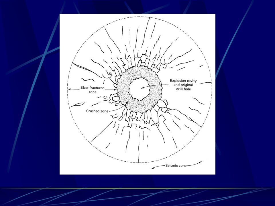
Detonation process Detonation produces hot gas and pressure
Rock around borehole is crushed and cracks extend outward. Gases extend into the cracks breaking and moving the rock, utilizing most of the energy available in the process. A small amount of energy escapes in the form of ground and air vibrations.

78
A small amount of energy escapes in the form of ground and air vibrations.
This energy is in the form of elastic waves – there is no further damage to the rock nor any permanent displacement of rock particles outside of the blasted area a distance of approximately 20 borehole diameters

79
Blast Designs

80
Blast Layout Terminology
Burden: Horizontal distance between a borehole and the quarry face Spacing: Horizontal distance between holes; perpendicular to the burden. Subgrade: Depth of holes below the final grade level. Collar:Length of unloaded borehole at the top of the hole. Stemming: Inert material placed on top of explosive column or between “decks”.

81
Drilling Parameters S T B H S = Spacing J B = Burden H = Hole Depth
T = Stemming (Collar) J = Sub-drilling J
 J = Sub-drilling. J.")
82
Drill Patterns (Square B = S)
Burden (B) Spacing (S) Free Face
 Spacing (S) Free Face.")
83
Nonelectric EZ-Det/Handi-Det Initiation System
In-the-hole Delay (500 ms) Surface Delay (25 ms) Shock-Tube EZ-Det/Handi-Det Cap Surface Delay (17, 33, 42 ms) Clip Surface Connector
 Surface. Delay (25 ms) Shock-Tube. EZ-Det/Handi-Det Cap. Surface Delay. (17, 33, 42 ms) Clip. Surface Connector.")
84
Grade Rock / Quarry V-Cut Sequence
F R E E F A C E 50 25 42 67 92 134 109 84 126 151 176 218 193 168 210 235 260 Start

85
Initiation Sequence - Dice Five “Trench”
Free Face 25 50 75 125 100 25 MS Delay Start

86
Controlled Blasting Techniques
Preshear, Postshear Line drilling

87
Typical Detonation Sequence
Controlled ….. Typical Detonation Sequence Remaining Preshear holes to be detonated with the next blast Preshear holes fired approx. 200 ms prior to production and buffer holes Production and buffer holes to be fired approx. 200 ms after the presplit holes are detonated Not to Scale - For Illustration Purpose Only

88
Line Drilling Controlled …..
Holes are drilled along the perimeter at close spacing prior to blasting. Holes are not loaded Production blast is used to fracture rock within the excavation area to the line drilled perimeter. Tends to provide the best final face but drilling costs are elevated. Care must be taken not to ‘hit’ the walls too hard and fracture rock beyond the neat line – may require the application of buffer holes.

89
Module VI Blast Vibration and Overpressure

90
The derivatives of blasting which cause the greatest amount of concern to property owners adjacent to blast sites are flyrock, ground vibrations and overpressure (air blast).
.")
91
Blast Vibrations The magnitude of ground vibrations is expressed in terms of Peak Particle Velocity in mm/s. Peak Particle Velocity is generally accepted world wide as the best way to express the potential for damage from blast vibrations. Peak Particle Velocity is defined as the rate of exchange of the amplitude. This is the speed of excitation of the particles in the ground resulting from vibratory motion caused by blasting.

92
Basis for Vibration Control
Blast vibration control is almost universally based on research undertaken by the United States Bureau of Mines as reported in publication RI8507. This research and associated data represents the most extensive information available directly relating blast induced damage to particle velocities. This research established threshold vibration intensities for different materials found in typical residential construction below which damage is highly improbable.

94
Basis for Vibration Control
The “Z” curve graph and associated criteria are extremely conservative and have been consistently proven to be such through countless additional research efforts undertaken in the years since the publication of RI8507. It has formed the basis for the majority of regulations and guidelines worldwide, including those established by the City of Ottawa and MOE. Scientifically observed damage as a result of blast induced has never been observed at ground motions below the Z-Curve limits.

95
Blast Overpressure Blast overpressure is a compressional wave in air caused by: an air pressure pulse caused by the direct rock displacement at the face or collar of a blast hole. A rock pressure pulse caused by the vibrating ground. A gas release pulse caused by explosives gases escaping through fractures in rock. A stemming release pulse caused by gas escaping from blown out stemming.

96
Blast Overpressure Blast overpressure is usually low frequency although there can be a high frequency component (noise). Overpressure is measured in dB(L). Overpressure is far more difficult to control when compared to ground vibrations and is heavily dependent on environmental conditions. As such, limits on overpressure are rarely imposed on construction projects.
. Overpressure is measured in dB(L). Overpressure is far more difficult to control when compared to ground vibrations and is heavily dependent on environmental conditions. As such, limits on overpressure are rarely imposed on construction projects.")
97
Wind Speed vs. Overpressure
WIND EQUIVALENT (Kph) OVERPRESSURE STANDARDS (dB) (Kpa) 650 180 20.68 Structural Damage 525 176 13.79 Plaster Cracks 250 164 3.45 Most Windows Break 115 150 0.62 Some Windows Break 65 140 0.21 OSHA Maximum For Impulsive Sound. This level could cause loose windows to vibrate. THRESHOLD OF PAIN 32 128 0.05 M.O.E.E. Guideline for Monitored Blasts 15 0.01 Complaints Likely 6.5 100 2.07 x 10⁻³ Pneumatic Hammer 0.65 60 2.07 x 10⁻⁵ Conversational Speech 0.02 2.07 x 10⁻⁸ Threshold of hearing
 OVERPRESSURE. STANDARDS. (dB) (Kpa) Structural Damage Plaster Cracks Most Windows Break Some Windows Break OSHA Maximum For Impulsive Sound. This level could cause loose windows to vibrate. THRESHOLD OF PAIN M.O.E.E. Guideline for Monitored Blasts Complaints Likely x Pneumatic Hammer x Conversational Speech x Threshold of hearing.")
98
147 dBL 150 140

99
Measurement of Blast vibrations
Seismographs monitor on a continual basis and record both ground vibration and overpressure intensities. These records allow reliable, accurate, legal documentation of blast effects and analytical tools for advanced analysis if required.

100
Why NOT monitor Cost Outside of revenue stream
Outside of regular duties / no qualified technician Equipment unavailable Don’t see benefit / repercussions Never had a problem Inconvenient / Don’t care / can’t be bothered

101
Why bother monitoring? Proper documentation has legal status.
Provides quantitative, scientific backup for public perception – Humans are not accurate seismographs. Good records form an integral part of the damage investigation procedure.

102
Compliance Monitoring – Ground vibrations
Sensor should be installed on or in the ground at the closest ‘structure’ on the side closest to the blast. If ground installation is not feasible, couple to structure within 300mm of the surrounding ground. Install sensor within 3m of the structure. Ensure suitable coupling of sensor – bolted, buried, spiked sandbagged.

103
Compliance monitoring – Overpressure
Sensor should be installed at the closest ‘structure’ on the side closest to the blast. Avoid placement near reflective surface. Avoid shielding by other buildings, trees, etc. Microphone height does not affect reading.

104
What constitutes a good record?
Record should include: Time and date Location of seismograph Vibration intensities in 3 mutually perpendicular planes Overpressure Vibration waveforms and frequencies Name of operator Calibration check

105
All vibrations records and blast reports should be maintained and filed for future reference to be incorporated into the damage investigation procedure. Missing, incomplete or faulty vibration and blast data all contribute to a difficult damage investigation procedure and public discontent

106
Understanding the Event Report

107
Autonomous Vibration Monitoring (AVM)
")
108
Autonomous Vibration Monitoring (AVM)
Couples internet with seismographs Automatic event distribution AVM Package Vibration Monitor Modem (cellular or land line) Power source Data processing system Website/cell phone/
 Power source. Data processing system. Website/cell phone/ .")
109
Event Transmitted to IPS
AVM Telemetry Blast Occurs Event Transmitted to IPS Through Phone Network IPS Resets Unit and Starts Monitoring Seismograph Triggers

110
AVM Data Processing FPS IPS Processes Creates GIF and PDF
XML and WMF Files XML and WMF Files Transmitted And Verified For Processing Event Sent to Cell Phone or FPS Updates Web Page

111
Web User Interface Secure site (HTTPS) View vibration data
User based filters

112
Web User Interface Sort Events by Date/Job/unit

113
Web User Interface Download options Filter events
PDF, GIF, Blastware file

114
Web User Interface Notification methods Cell phone text message email
Sample text message

115
Human Response to Blast Vibrations and Overpressure

116
Human Response to Blast Vibrations and Overpressure
Human beings are very sensitive to blast vibrations. Vibrations as low as 0.5 mm/sec are perceptible and annoying to some people.

117
Human Response to Blast Vibrations and Overpressure
Blast overpressure may only be noticed because windows, knick knacks or doors may rattle. This is caused by the low frequency impact which blast overpressure applies to buildings having a resonant frequency of 10 – 15 Hz. Blast overpressure rarely causes blast damage but at levels of 115 dB or more complaints increase.

118
Does Moose want a title on this?

119
Does Moose want a title on this?

120
Module VII Public Relations

121
Public Awareness Why do people get upset?
They were not informed of the blasting They do not understand why they need to blast They do not understand regulatory vibration limits Believe that if they can feel the vibrations, there MUST be damage to their home Annoyed by the development or construction activities Stress in their own personal and professional lives People automatically assume that if they can feel the vibrations from the blasting operations, it MUST be damaging their house.

122
What you can do to ease the public concerns
Notify public of blasting operations (visible signs and written notices) Educate and explain instead of dismissing concerns - Provide literature, web sites and videos explaining construction blasting. Explain your monitoring program. Provide access to blast records: event reports, threshold levels for damage to structures. Promptly address complaints or concerns. Listen to their concerns.
 Educate and explain instead of dismissing concerns - Provide literature, web sites and videos explaining construction blasting. Explain your monitoring program. Provide access to blast records: event reports, threshold levels for damage to structures. Promptly address complaints or concerns. Listen to their concerns.")
123
PR Components of a proper Blast Control Plan
Pre-blast inspections Vibration / Overpressure monitoring Provide a means of efficiently and effectively addressing public concerns and questions. Address Damage complaints in a timely manner.

124
Pre-blast Inspections

125
Pre-Blast Inspections
F-1011 (March 2011) Pre-Construction Inspections All structures within 30m of general work F-1201 (March 2011) Pre-Blast Inspections All structures within 65m of blasting operations
 Pre-Construction Inspections. All structures within 30m of general work. F-1201 (March 2011) Pre-Blast Inspections. All structures within 65m of blasting operations.")
126
Pre-Blast Inspections
Inhabitants of buildings close to blasting may feel vibrations from the operation and as a result, become much more conscious of many of the previously unnoticed cracks, water stains, and similar defects in their homes and offices. Pre-blast inspections are intended to provide a representative sampling of pre-existing deficiencies which are present in every residence.

127
Pre-Blast Inspections
These inspections are not intended to provide a detailed, exhaustive list of every crack present. In the event of concern by residents with regards to possible damage as a result of the construction, the pre-construction inspections are used to form the basis for an investigation.

128
Damage Complaints Regardless of how well a blasting operation goes, there will inevitably be complaints from at least some residents in the area. This is due to a variety of factors including: Public disapproval with the project. Public annoyance due to the construction. Dishonest owners. General public unfamiliarity with blasting.

129
Fears expressed concerning blasting damage are often a result of the sensitivity of the human body to vibration, especially in the low frequency range. Inhabitants of buildings close to the blasting may feel vibrations from the operation and as a result, become much more conscious of many of the previously unnoticed cracks, water stains, or similar defects

130
Damage Investigations
Regardless of the perceived frivolousness or credibility of a complaint, all complaints should be addressed. This may be as simple as a visit to discuss the matter with the owner or may require more in depth analysis. In any case, damage investigations should be performed by qualified individuals independent from the affected parties (owner/ contractor).
.")
131
Damage Investigations
If required, a full damage investigation should incorporate: Visual inspection and documentation of the damaged area. Comparison with pre-blast inspections. Analysis of Vibration data. Analysis of Blast reports Review of applicable related research.

132
Damage Investigations
All significant impacts on the residence should be included as part of the investigation Differential thermal expansion, structural overloading, chemical changes in building materials, shrinkage and swelling of wood, fatigue and aging of building materials, foundation settlement and the impacts of human habitation all induce transient deformation similar to those induced by construction operations. The key difference lies in the lack of startle associated with environmental and occupancy effects.

133
Damage Investigations
Damage reports are typically submitted to the blast contractor and complainant. Copies of the report should be provided to the Project Contract Administrator if requested.

134
The adoption of a properly planned, controlled and executed blast program can lead to project results which are viewed as successful by the project owners, contractors, and affected adjacent residents alike.

135
Questions?

Similar presentations


 MOSH - Day of Learning 2014.>")


 OF 1970 George Mason University College of Nursing and Health Science Regulatory Requirements.>")


