Download presentation
Presentation is loading. Please wait.

1
Chapter 6 Control of Secondary and Scattered Radiation

2
CONTROL OF SECONDARY AND SCATTERED RADIATION
There are various types of auxiliary radiographic equipment that can be used to control the secondary and scattered radiation. These include filters, diaphragms, cones, and grids.

4
FILTERS are thin sheets of material (copper, aluminum) placed between the tube and the patient, through which the x-ray must pass before they reach the film. They absorb some of the soft/weak, undesirable radiation, depending upon the material they are made of.
 placed between the tube and the patient, through which the x-ray must pass before they reach the film. They absorb some of the soft/weak, undesirable radiation, depending upon the material they are made of.")
5
FILTERS All filters absorb radiation of all wavelengths. They absorb, however, relatively more of the soft rays (longer wavelengths). The filter therefore removes the rays that can cause skin reactions or damage and which are subject to greater scattering because of their limited energies.
. The filter therefore removes the rays that can cause skin reactions or damage and which are subject to greater scattering because of their limited energies.")
6
FILTERS Part of the filter is permanently built into the tube head - the inherent filter. this includes the glass wall of the tube, the oil surrounding the tube and the wall of the tube head. These materials are thinned over the area penetrated by the x-ray beam (the x-ray window or port). The inherent filtration amounts to approximately the equivalent of 0.5 mm. of aluminum.
. The inherent filtration amounts to approximately the equivalent of 0.5 mm. of aluminum.")
7
FILTERS Directly in front of the x-ray window is a channel for adding other filters. These are made of aluminum for radiography (and of aluminum, copper, tin, and even lead for radiotherapy). For patient safety, you should always maintain an additional 2.0 mm. aluminum filter which, together with the inherent filtration, gives a total filtration of 2.5 mm. of aluminum.
. For patient safety, you should always maintain an additional 2.0 mm. aluminum filter which, together with the inherent filtration, gives a total filtration of 2.5 mm. of aluminum.")
8
FILTERS The introduction of 1 mm of aluminum filtration reduces the dosage to the patient by 60%, and 2mm. of aluminum reduces the dosage to the skin by 80% at 50Kv and 70% at 100 kV.

9
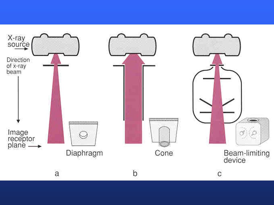
DIAPHRAGMS These are no longer in use today. Diaphragms are flat sheets of lead with various size and shape apertures in their centers. The size of the aperture used will be determined by the size of the area being examined and the film-anode distance. The diaphragm is placed in a slot between the patient and the tube and used as a mask, very much like a custom made collimator.

12
CONES Cones may be used in place of the diaphragm and are placed in the same slot that the diaphragm is used in. Cones are metal tubes and there are three basic types. A flare cone is one in which the aperture in the end facing the patient is larger than the end attached to the tube head. It allows for a larger field than the cylinder cone. Remember that the beam exiting through a cylinder cone may bounce off the cylinder cone and thereby give weaker rays to the patient

13
CONES A cylindrical cone (or cylinder) is one in which the aperture is the same throughout its length. A cylindrical extension cone is actually one cylinder within another slightly larger cylinder. The inner cylinder is attached to the tube head and the outer cylinder can be extended to contact the skin of the patient. This is used in spot-film work exclusively.
 is one in which the aperture is the same throughout its length. A cylindrical extension cone is actually one cylinder within another slightly larger cylinder. The inner cylinder is attached to the tube head and the outer cylinder can be extended to contact the skin of the patient. This is used in spot-film work exclusively.")
14
CONES Diaphragms and cones serve to limit the x-ray field to the part which is being radiographed by cutting down the field size. They also cut down on the quantity of soft tissue exposed and thus reduce the amount of scattered radiation and reducing film fog. Since scattered radiation accounts in part for the radiographic effect produced, primary exposure must be increased (20% in a 3 inch field).
.")
15
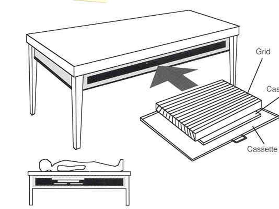
GRIDS are devices that are placed behind the patient and in front of the film to minimize the amount of secondary radiation from the soft tissues reaching the film. The grid appears to be a solid piece of metal but is actually composed of lead strips alternating with a radiolucent material (wood or bakelite).
.")
18
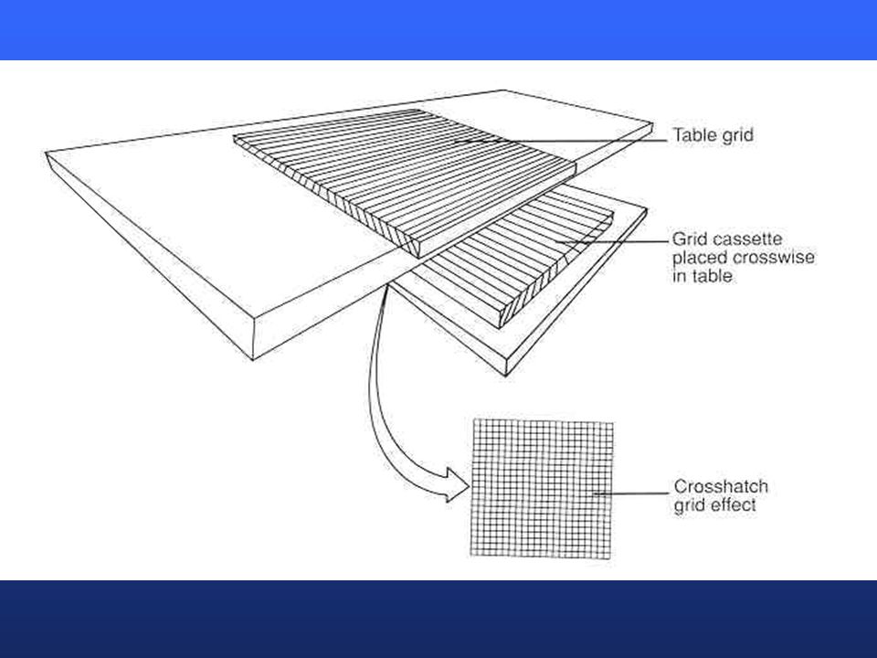
GRIDS There are two basic types of grids: Focused Unfocused

19
GRIDS A grid is unfocused when all the lead strips are parallel to each other and perpendicular to the grid surface. A grid is focused when all the lead strips except those in the center are inclined at an angle towards the center (they are actually on radius of a circle whose center is the focal spot of the tube when the correct distance is used).
.")
21
GRIDS Using a parallel or unfocused grids gives us the ability to change distances. This may not be as good a remover of scatter as the focused, but it gives us more freedom.

22
GRIDS The focused grid can be used in only one way - the side on which the lead strips are closer must face the tube and the proper distance for the grid should be used. If the focused grid is used backwards or at an improper distance, the radiation at the edges of the film will be absorbed and the film will be blank at these places.

26
Grid Radius is the distance from the center of the grid to a point where the projected planes of the focused strips of the grid would meet. Grid radii of 30, 36, 40 and 48 inches are in use. Although a 40 inch grid radii is the most common used today, most people don’t use focused grids at all.

27
Grid Radius The focal spot of the tube should be at the focus of the grid; then the divergent beam of the primary rays is parallel to the lead strips and a minimum of them will be absorbed by the strips. In an unfocused grid the radius would be infinity. The focused grid will be marked “tube side” on the side that must face the tube.

28
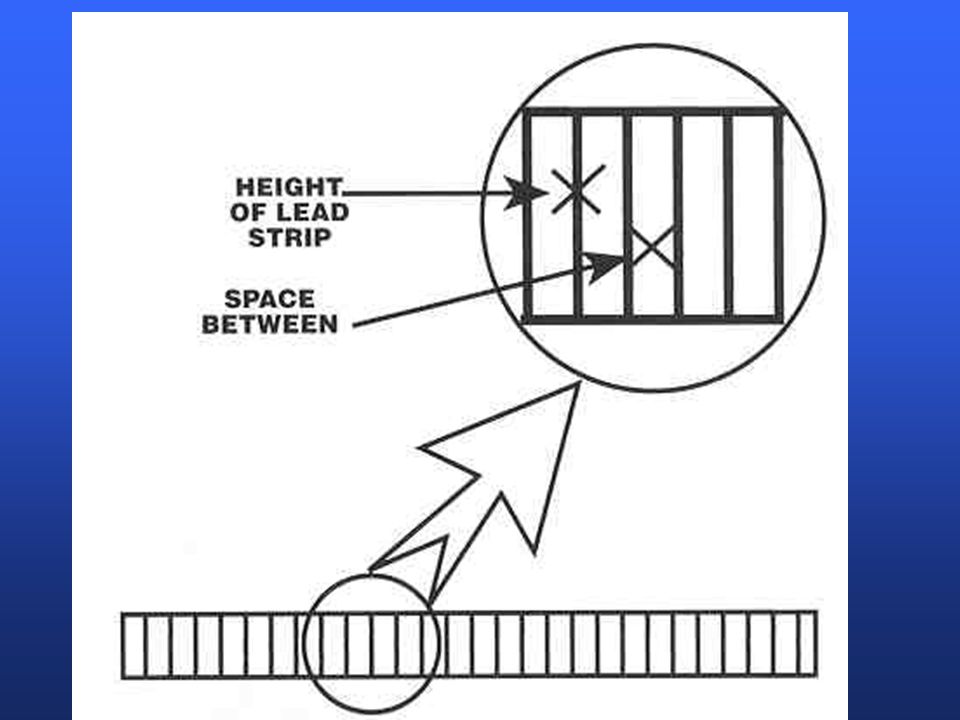
Grid Ratio is the ratio of the height of the lead strips to the width of the space between them. Various ratios include, but are not limited to, 8:1, 10:1, 12:1, 16:1. The most common grid ratios are 8:1 and 10:1.

30
Grid Efficiency refers to the amount of maximum absorption of secondary radiation as compared with minimal absorption of primary radiation. When the secondary radiation is materially reduced without any appreciable absorption of primary radiation, the efficiency is high. Classically, the higher the grid ratio, the more efficient the grid as it decreases the amount of obliquely scattered rays by four times.

31
Stationary Grids AKA “Wafer” grids or Leisholm grids
produce x-rays that have very fine white lines on them. These are the area of the film that are blocked from receiving any x-ray by the lead strips. To eliminate these “grid lines” the moving grid or Potter-Bucky diaphragm was developed by Potter in 1913.

32
Potter-Bucky The Potter-Bucky has all the characteristics of the stationary grid with the addition of a system to move the grid across the film when the exposure is being made. When this happens no part of the film is entirely deprived of radiation, and there are no grid lines of the finished film. The Bucky is often connected into the timing circuit of the x-ray machine, but it is a mechanical device, depending upon the electricity only for its release.

33
Potter-Bucky It should be remembered when calculating an exposure that the M.A.S. required when using a Bucky or grid will be four times the amount required without it, but the increase in contrast and detail will make it worth using. Never x-ray a part thicker than 10 or 11 centimeters without using a bucky or grid due to the large amount of scattered radiation that needs to be eliminated.

34
Grids Today, stationary grids are being used as the lead lines are made so thin that they are invisible to the naked eye. Stationary grids are being produced at up to 140 lines per inch and do an excellent job in absorbing scatter.

38
THE INVERSE SQUARE LAW The Inverse Square Law states that the intensity of radiation decreases in proportion to the square of the distance. Remember that x-ray travels in a straight line diverging from a point.

40
THE INVERSE SQUARE LAW When using 40” and 72” it is easy to see that this is a basic doubling of the distance. When shooting at 72” you are shooting an area four times larger than that shot at 40”. Therefore, you need to increase the MAS by four times to compensate. When using four times more MAS you should collimate down four times more so that the patient does not receive more radiation.

Similar presentations


>")


