Download presentation
Presentation is loading. Please wait.

1
PDP Training Manual P450

2
Agenda 2. Disassembly 3. Trouble shooting 4.Appendix -. PC Timming
1. P450 Training 2. Disassembly 3. Trouble shooting 4.Appendix -. PC Timming -. 3D Function

3
1. PB450 Training

4
CVBS,S-Video, Headphone, HDMI
● Comparison with other Models Project PB450 (U1P) PYROPE (W3) Design Brightness 1500cd/m2 Contrast ratio 15000:1 Tuner 1 Nim Tuner (Slim) Audio out 10W x 2 Sound SRS Tru Surround XT Speaker Included Video input 1Side S-Video input X Component Input 1Rear Side Input CVBS, HDMI CVBS,S-Video, Headphone, HDMI HDMI 2Rear + 1Side Power Consumption 42” : 350W 50” : 450W 42” : 380W 50” : 480W Etc. -
 PYROPE (W3) Design. Brightness. 1500cd/m2. Contrast ratio :1. Tuner. 1 Nim Tuner (Slim) Audio out. 10W x 2. Sound. SRS Tru Surround XT. Speaker. Included. Video input. 1Side. S-Video input. X. Component Input. 1Rear. Side Input. CVBS, HDMI. CVBS,S-Video, Headphone, HDMI. HDMI. 2Rear + 1Side. Power Consumption. 42 : 350W. 50 : 450W. 42 : 380W. 50 : 480W. Etc. -")
5
● Picture of PS50B450 Set [Back view]
![● Picture of PS50B450 Set [Back view]](http://slideplayer.com/slide/4034093/13/images/5/%E2%97%8F+Picture+of+PS50B450+Set+%5BBack+view%5D.jpg "● Picture of PS50B450 Set [Back view]")
6
● Picture of P450 42” U1P PDP Module [Back view]
![● Picture of P U1P PDP Module [Back view]](http://slideplayer.com/slide/4034093/13/images/6/%E2%97%8F+Picture+of+P+U1P+PDP+Module+%5BBack+view%5D.jpg "● Picture of P U1P PDP Module [Back view]")
7
● Picture of P450 50” U1P PDP Module [Back view]
![● Picture of P U1P PDP Module [Back view]](http://slideplayer.com/slide/4034093/13/images/7/%E2%97%8F+Picture+of+P+U1P+PDP+Module+%5BBack+view%5D.jpg "● Picture of P U1P PDP Module [Back view]")
8
● Picture of PS42B450/PS50B450 Chassis
LVDS 4.Flash 2.DDR 2.DDR 1.SATURN4 3.Sound AMP

9
1 IC5001 IC-LCD CONTROLLER SEMS01,LQFP,256P,30x30mm,PLASTIC,3.3V,2.2W,0to+70C,TR 2 IC6001 IC-VIDEO PROCESS S4LF119X01,PBGA,208P,17x17mm,PLASTIC,3.6V,0to+70C,TR,FBEx 3 IC7001 IC-DECODER UPD61211GM-104-GAA-A,QFP,216P,24x24mm,PLASTIC,3.3V,700mA,0to+70C,TR 4 IC3001 SWITCH SiI9185CTU,QFP,80P,3.3V,0 to +70C,PLASTIC,TR 5 IC5201 IC-DDR SDRAM EM6A9160TS0A-5G,DDR SDRAM,128Mbit,8Mx16,TSOP2,66P,22.22x10.16mm,5nS,2.375/2.625V,0to+70C,90mA TR 6 IC7002 IC-DRAM HYB25D256163CE,DDR,256Mbit,16Mx16Bit,TSOP,66P,22.22x10.16mm,4ns,2.5/2.7V, -,0to+7 7 IC2001 IC-POWE AMP NTP3100,QFN56,56P,8x8mm,DUAL,PLASTIC,24V,40W,-10to+85C

10
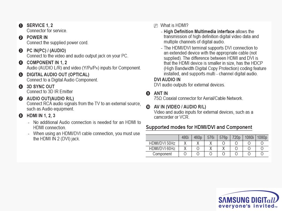
● Calibration (Component/HDMI/AV/PC)
■ White Balance – Calibration If picture color is wrong, do calibration first. Execute calibration in Factory Mode (AV mode example): 1. Source : VIDEO (AV mode) 2. Setting Video Mode (Timing) : PAL Video (MODE : #2) 3. Setting pattern : Pattern #24 (Chess Pattern) 4. Use Equipment : K-7256 or Equipment of equality level 5. Work order: 1) Enter Factory Mode and select “2. WB Adjust“ -> “Calibration” 2) Select "AV CALIBRATION" and press the right button on the remocon ( ) 3) After completing calibration, the “Success…” message will be displayed next by “AV CALIBRATION” For Component/HDMI mode use resolution of 1280x720/60Hz (MODE: #6) For PC mode use resolution of 1024x768/60Hz (MODE: #21)
: 1. Source : VIDEO (AV mode) 2. Setting Video Mode (Timing) : PAL Video (MODE : #2) 3. Setting pattern : Pattern #24 (Chess Pattern) 4. Use Equipment : K-7256 or Equipment of equality level. 5. Work order: 1) Enter Factory Mode and select 2. WB Adjust -> Calibration 2) Select AV CALIBRATION and press the right button on the remocon ( ) 3) After completing calibration, the Success… message will be displayed next by AV CALIBRATION For Component/HDMI mode use resolution of 1280x720/60Hz (MODE: #6) For PC mode use resolution of 1024x768/60Hz (MODE: #21)")
11
The WB specification can be found on the G-TMS system.
● White Balance Adjustment The WB specification can be found on the G-TMS system.

12
● Picture condition in Factory mode / during WB adjust
● Factory mode OSD

17
Accessories

18
2. Disassembly

19
Separation of ASSY COVER P-REAR

20
Separation of ASSY PCB MISC-MAIN

21
Separation of FILTER-EMI AC LINE

22
Separation of BRACKET-PCB

23
Separation of ASSY BRACKET 42"/50"

24
Separation of ASSY BRACKET P-WALL

25
Separation of ASSY SPEAKER P

26
Separation of SMPS-PDP TV

27
Separation of ASSY PDP MODULE
P-LOGIC MAIN BOARD

28
Separation of ASSY PDP MODULE P-X MAIN BOARD

29
Separation of ASSY PDP MODULE P-X MAIN BOARD

30
Separation of ASSY PDP MODULE P-Y MAIN BOARD

31
Separation of ASSY PDP MODULE P-Y MAIN BOARD

32
Separation of ASSY PDP MODULE P-Y MAIN BOARD

33
Separation of ASSY PDP MODULE P-ADDRESS BUFFER BOARD

34
Separation of ASSY PANEL BRACKETS

35
3. Trouble shooting

36
● PS50A450 SW update method using the D/L jig
1. Connect the PC and PDP using D-SUB Cable and D/L jig Step by Step Picture of D/L jig D-SUB Cable 2. Run the Flash download program ISP_Tool v4.3.0

37
3. Click “Connect” button
4. Now the connection with the SET is established. Click the “확인”

38
5. Connect the Power cord and click “Read”
6. Click the new “Read” button

39
7. Select the upgrade file

40
8. Click “Auto” button, uncheck the Blank and Verify options and click “Run”

41
9. The download progress bar appears and D/L information is shown in the info window

42
● PS50A450 SW update method using the USB

44
● Check List in advance ■. Each cable connection condition check
- Cable is connected correctly ? ■.Check Voltage - SMPS Video main Board, SMPS X,Y Drive board, SMPS Logic board ■. The chart below shows abnormal condition

45
● No Power - Not operate front LED Not operate SMPS relay

46
● SMPS relay on <-> off continually
Operate Protection circuit because of some Ass’y problem

47
● No display but sound is normal
X or Y or Logic or Y Buffer board is abnormal SMPS output Voltage is abnormal

48
● No sound but display is normal
Speaker wire is not connect Video main board sound part defect Speaker part defect Volume level is “0”(Non-sense)
")
49
● PDP Dot Module SPEC – SDI module
※ Special Management Items 1) It is Cell-Defect if there are dark, bright, flickering cells over 2 points within 1.5cm in the boundary section. 2) Before vibration/dropping test, it should be decided whether the module is good / badness first. And after vibration/dropping test, if Cell-Defect happens more than preceding descriptions on Specification, it is Cell-Defect module.
 It is Cell-Defect if there are dark, bright, flickering cells over 2 points within. 1.5cm in the boundary section. 2) Before vibration/dropping test, it should. be decided whether the module is good. / badness first. And after vibration/dropping test, if Cell-Defect happens more than. preceding descriptions on Specification, it is Cell-Defect module.")
50
● A-Zone / B–Zone Size

51
PC timming

53
3D Function

Similar presentations


 47LX9500-UA : The Full model name.>")


