Download presentation
Presentation is loading. Please wait.

1
NEWLINK Technical Training
Cabling Systems NEWLINK J1 NEWLINK Technical Training Copyrights 2003

2
Objetive Prepare participants to take the Certified Installer Test
Cabling Systems NEWLINK Prepare participants to take the Certified Installer Test Introduce concepts and requirements in Wireless Installations Authorize Certified Installers for NEWMAX Warranty Program

3
Benefits Get free technical support for your projects
Cabling Systems NEWLINK Get free technical support for your projects Get NEWMAX Warranty for your jobs Receive updates and news from our Industry Receive Sales Leads contacts in your Area As a NEWMAX CERTIFIED INSTALLER receive the benefits of our team of professionals

4
Contents Telecommunications Basics
Cabling Systems NEWLINK Telecommunications Basics Physical Media : Copper, Fiber Optics Standards reviews TIA/EIA 568, 569, 606 Testing Procedures for UTP and Fiber Optics Wireless Networks Guidelines Practice with NEWLINK products NEWLINK Certification Test

6
Importance of Certified Jobs
Cabling Systems NEWLINK Importance of Certified Jobs For the End-user Good installation practice endorsement Simplified Effective Troubleshooting Organized network makes Moves & Changes easier For the IT management Defined life-cycle investment Fullfillment of international standards Follows globally used technology trends for future applications Quality assurance, based on 100% circuits testing For the Certified Installer Well trained personnel saves money NEWMAX 25-years Warranty gives ADDED VALUE

7
Schedule DAY 1 Introduction to Networking Standard TIA/EIA 568 Summary
Cabling Systems NEWLINK DAY 1 Introduction to Networking Standard TIA/EIA 568 Summary Testing UTP and Fiber Installations Standards 569 and 606 Summary DAY 2 Fiber Termination Laboratory Wireless Technology Seminar Test

8
Introduction to Networking

9
Telecommunication’s Evolution
Electricity Based Telecommunications 1844 Samuel Morse : Telegraph and Morse Code 1860 Thomas A. Edison : Printing Telegraph 1876 Alexander G. Bell : Telephone, starts the Bell Company 1889 Almon B. Strowger : Dialer Telephone 1890 Herman Hollerith : Punched Cards for Computing 1905 Emile Baudot : Teletype (TTY) and Baudot Code 1911 Guillermo Marconi : Radiotelegraphy 1948 Bell Labs : Invention of the Transistor
 and Baudot Code Guillermo Marconi : Radiotelegraphy Bell Labs : Invention of the Transistor.")
10
Telecommunication’s Evolution
1950 First Computers 1960 First Modems and Fiber Optics experiences 1962 Time Sharing concept development 1966 Standard Codes ASCII ... UNICODE, IBM EBCDIC 1969 EIA RS-232C (recommended standard) 1972 First commercial VDTs 1977 Telephony equipment multivendor aperture through FCC Part 68 1978 First PCs 1983 PC/AT Arquitecture, first IBM clones and MS-DOS 1984 Break Out of Telephony monopoly in USA 1985 First Telecommunication Cabling Standards 1990 Internet
 1972 First commercial VDTs Telephony equipment multivendor aperture through FCC Part First PCs PC/AT Arquitecture, first IBM clones and MS-DOS Break Out of Telephony monopoly in USA First Telecommunication Cabling Standards Internet.")
11
Telecommunication’s Evolution
1991 CAT Mhz 1994 CAT 4 – 1995 First WLANs 1997 CAT Mhz 1998 NEWLINK USA 1999 Vo/IP Apllications 2000 CAT 5E Mhz enhanced 2002 CAT Mhz 2003 Fiber Optics Enhanced for 10 Giga Currently a Task Force Group is working in the development of a 10Gigabit Ethernet over Copper (P802.an) standard expected by the end of 2006.
 standard expected by the end of")
12
The Early Evolution was isolated…
Telecomm DATA VOICE IMAGES SIGNALS Las telecomunicaciones evolucionan a partir de la necesidad de las gentes de comunicarse rápida y eficientemente. Desde las transmisiones de claves telegráficas hasta la integración de Voz, Datos, Video en plataformas de Red, las telecomunicaciones vienen sufriendo (ó gozando) de una transformación inmensa, globalizante. La historia de cambios a lo largo de una evolución exponencialmente acelerada nos asegura que la tecnología de hoy será renovada totalmente y en corto tiempo.
 de una transformación inmensa, globalizante. La historia de cambios a lo largo de una evolución exponencialmente acelerada nos asegura que la tecnología de hoy será renovada totalmente y en corto tiempo.")
13
Then Interacting… SIGNALS VOICE DATA IMAGES
Access Control, Smart Cards, Digital Security Digitized Voice, VoIP, Music on demand VOICE DATA Fax, Multimedia, DVD, video-conference Las telecomunicaciones evolucionan a partir de la necesidad de las gentes de comunicarse rápida y eficientemente. Desde las transmisiones de claves telegráficas hasta la integración de Voz, Datos, Video en plataformas de Red, las telecomunicaciones vienen sufriendo (ó gozando) de una transformación inmensa, globalizante. La historia de cambios a lo largo de una evolución exponencialmente acelerada nos asegura que la tecnología de hoy será renovada totalmente y en corto tiempo. Digital TV, Telex, Digital cameras Broadband Video IMAGES
 de una transformación inmensa, globalizante. La historia de cambios a lo largo de una evolución exponencialmente acelerada nos asegura que la tecnología de hoy será renovada totalmente y en corto tiempo. Digital TV, Telex, Digital cameras. Broadband Video. IMAGES.")
14
Now Integrated SIGNALS IMAGES VOICE DATA Dictaphones Beepers
Hospital Nurse Calling Systems Time Control Systems Access Control and Surveillance Alarm panels, burglary, monitoring Personal Protection Systems Automation, Instrumentation, Control SIGNALS Now Integrated IMAGES VOICE Audio visual Integrated Systems CATV, CCTV, Digital TV, TV-SAT Hospitality Systems Medical Imaging Outside Plant / Off-Premises Systems Telephony Intercoms Public Address Systems ( PAS) Music Cellular technology Los códigos americanos para construcción dictados por la CSI (Construction Specifications Institute) están evolucionando hacia una Integración Total de los diversos Sistemas y Sub-sistemas de comunicaciones de los edificios modernos. Se ha desarrollado un Master Format para la implementación de capítulos independientes, derivados de la Division 17 y dedicados a: Communications Life Safety Integrated Automation Systems Las principales caracteristicas del CLA serán : Basadas en estándares Centradas en el Propietario Involucrado en el Proyecto Influenciadas por los Fabricantes Internet - Intranet Data Transmission Communication Services Wireless Networks DATA
 Music. Cellular technology. Los códigos americanos para construcción dictados por la CSI (Construction Specifications Institute) están evolucionando hacia una Integración Total de los diversos Sistemas y Sub-sistemas de comunicaciones de los edificios modernos. Se ha desarrollado un Master Format para la implementación de capítulos independientes, derivados de la Division 17 y dedicados a: Communications. Life Safety. Integrated Automation Systems. Las principales caracteristicas del CLA serán : Basadas en estándares. Centradas en el Propietario Involucrado en el Proyecto. Influenciadas por los Fabricantes. Internet - Intranet. Data Transmission. Communication Services. Wireless Networks. DATA.")
15
Simplified Telecommunications Model
Message to be Sent Received Message Telecomm Transmitter Receiver Physical Media La comunicación eficáz requiere que el mensaje transmitido llegue al Receptor oportunamente, sea inteligible, del “volúmen” mínimo necesario para que sea interpretado. En la transmisión de Datos los Octetos (Bytes) compuestos de 1 y 0 (unos y ceros) significan diferente en función al orden de los números binarios. p.e no es lo mismo que aunque ambos cuenten con 6 números 1 y dos ceros!!
 compuestos de. 1 y 0 (unos y ceros) significan diferente en función al orden de los números binarios. p.e no es lo mismo que aunque ambos cuenten con 6 números 1 y dos ceros!!")
16
The Basic Issue in Telecommunications
Interruption Telecomm Message Transmitter Receiver La comunicación eficáz requiere que el mensaje transmitido llegue al Receptor oportunamente, sea inteligible, del “volúmen” mínimo necesario para que sea interpretado. En la transmisión de Datos los Octetos (Bytes) compuestos de 1 y 0 (unos y ceros) significan diferente en función al orden de los números binarios. p.e no es lo mismo que aunque ambos cuenten con 6 números 1 y dos ceros!! Delays Degradation Distortion
 compuestos de. 1 y 0 (unos y ceros) significan diferente en función al orden de los números binarios. p.e no es lo mismo que aunque ambos cuenten con 6 números 1 y dos ceros!! Delays. Degradation. Distortion.")
17
Noise overcomes Signal !!
What Happens ? Transmitted signal Received Signal Atenuation length, frequency Tx Rx Limited Power Limited Sensitivity Noise EMI, RFI La Potencia de Salida está limitada porque de otra forma induce ruido adicional en los pares cercanos. (diafonía NEXT, FEXT) La Sensibilidad de Recepción requiere que la Señal doble en magnitud al Ruido de Fondo (ACR de 3 dB) La lectura errónea de Datos da lugar a retransmisiones que generan mayor tráfico en la Red, más colisiones y por ende menos eficiencia. En redes ruidosas de BAJA CATEGORIA las tasas efectivas de comunicaciones pueden hacer que colapse la red LAN. Noise overcomes Signal !!
 La Sensibilidad de Recepción requiere que la Señal doble en magnitud al Ruido de Fondo (ACR de 3 dB) La lectura errónea de Datos da lugar a retransmisiones que generan mayor tráfico en la Red, más colisiones y por ende menos eficiencia. En redes ruidosas de BAJA CATEGORIA las tasas efectivas de comunicaciones pueden hacer que colapse la red LAN. Noise overcomes Signal !!")
18
Telecommunication Requirements
Signal Transmission Level Media Noise Level Signal Reception Level ACR La Potencia de Salida está limitada porque de otra forma induce ruido adicional en los pares cercanos. (diafonía NEXT, FEXT) La Sensibilidad de Recepción requiere que la Señal doble en magnitud al Ruido de Fondo (ACR de 3 dB) La lectura errónea de Datos da lugar a retransmisiones que generan mayor tráfico en la Red, más colisiones y por ende menos eficiencia. En redes ruidosas de BAJA CATEGORIA las tasas efectivas de comunicaciones pueden hacer que colapse la red LAN.
 La Sensibilidad de Recepción requiere que la Señal doble en magnitud al Ruido de Fondo (ACR de 3 dB) La lectura errónea de Datos da lugar a retransmisiones que generan mayor tráfico en la Red, más colisiones y por ende menos eficiencia. En redes ruidosas de BAJA CATEGORIA las tasas efectivas de comunicaciones pueden hacer que colapse la red LAN.")
19
Data Transmission Transmitter Receiver Telecomm ....11001110...
Data Packet Telecomm Transmitter Receiver Message Integrity Communication Speed Shared Time Confirmation of Delivery Automatic Routing Encoding / Encripting Low Cost Las comunicaciones en cobre pueden llegar a frecuencias límite alrededor de los 600 Mhz, alcanzando los umbrales de las frecuencias de 800 Mhz usadas por la telefonía celular. Los equipos activos brindarán comunicaciones eficaces con una tasa menor de errores y retransmisiones. Se prevé un incremento gradual al uso de la fibra óptica a nivel de usuario. Las tecnologias wireless irán solucionando sus principales problemas de ancho de banda y seguridad de acceso para ser cada vez mas comunes en las oficinas. Interference

20
Internetworking WEB LAN ISP
Global Reach, multiprotocol, multi technology ... LAN WEB ISP Ethernet, Token Ring FDDI, SONET, ARCnet, BACnet, LONtalk X.25, TCP/IP, ATM Frame Relay, ISDN PSTN V32, ISDN Las comunicaciones en cobre pueden llegar a frecuencias límite alrededor de los 600 Mhz, alcanzando los umbrales de las frecuencias de 800 Mhz usadas por la telefonía celular. Los equipos activos brindarán comunicaciones eficaces con una tasa menor de errores y retransmisiones. Se prevé un incremento gradual al uso de la fibra óptica a nivel de usuario. Las tecnologias wireless irán solucionando sus principales problemas de ancho de banda y seguridad de acceso para ser cada vez mas comunes en las oficinas.

21
What is coming on ? Complete Integration of Signals, Voice, Images, Data Higher Speeds More efficient Protocols All Media Capacity Utilization Crescent Use of Fiber Optics Smarter Switches and Equipment Great development for Wireless Technologies Las comunicaciones en cobre pueden llegar a frecuencias límite alrededor de los 600 Mhz, alcanzando los umbrales de las frecuencias de 800 Mhz usadas por la telefonía celular. Los equipos activos brindarán comunicaciones eficaces con una tasa menor de errores y retransmisiones. Se prevé un incremento gradual al uso de la fibra óptica a nivel de usuario. Las tecnologias wireless irán solucionando sus principales problemas de ancho de banda y seguridad de acceso para ser cada vez mas comunes en las oficinas.

22
Vision ... Integrated Telecommunications over a common architecture, moving large amounts of Information (data packets) with reliability, quality over High-Speed Paths. Las comunicaciones en cobre pueden llegar a frecuencias límite alrededor de los 600 Mhz, alcanzando los umbrales de las frecuencias de 800 Mhz usadas por la telefonía celular. Los equipos activos brindarán comunicaciones eficaces con una tasa menor de errores y retransmisiones. Se prevé un incremento gradual al uso de la fibra óptica a nivel de usuario. Las tecnologias wireless irán solucionando sus principales problemas de ancho de banda y seguridad de acceso para ser cada vez mas comunes en las oficinas.
 with reliability, quality over High-Speed Paths. Las comunicaciones en cobre pueden llegar a frecuencias límite alrededor de los 600 Mhz, alcanzando los umbrales de las frecuencias de 800 Mhz usadas por la telefonía celular. Los equipos activos brindarán comunicaciones eficaces con una tasa menor de errores y retransmisiones. Se prevé un incremento gradual al uso de la fibra óptica a nivel de usuario. Las tecnologias wireless irán solucionando sus principales problemas de ancho de banda y seguridad de acceso para ser cada vez mas comunes en las oficinas.")
23
What is Structured Cabling ?
Passive Installation of Cables and Connectors Organized and Systematic Follows International Standards and Procedures Generic Model Open to diverse Applications Use well defined Elements, parts and tools Las comunicaciones en cobre pueden llegar a frecuencias límite alrededor de los 600 Mhz, alcanzando los umbrales de las frecuencias de 800 Mhz usadas por la telefonía celular. Los equipos activos brindarán comunicaciones eficaces con una tasa menor de errores y retransmisiones. Se prevé un incremento gradual al uso de la fibra óptica a nivel de usuario. Las tecnologias wireless irán solucionando sus principales problemas de ancho de banda y seguridad de acceso para ser cada vez mas comunes en las oficinas.

24
STRUCTURED CABLING CODES & STANDARDS CABLES AND COMPONENTS SPACES
CONNECTIVITY TESTING PROCEDURES Las comunicaciones en cobre pueden llegar a frecuencias límite alrededor de los 600 Mhz, alcanzando los umbrales de las frecuencias de 800 Mhz usadas por la telefonía celular. Los equipos activos brindarán comunicaciones eficaces con una tasa menor de errores y retransmisiones. Se prevé un incremento gradual al uso de la fibra óptica a nivel de usuario. Las tecnologias wireless irán solucionando sus principales problemas de ancho de banda y seguridad de acceso para ser cada vez mas comunes en las oficinas.

25
BENEFITS MANUFACTURERS Telecomm USERS BUILDING CONTRACTORS SUMMARY :
Performance Level Guaranteed Documented Easy Moves & Changes Adm Simple Maintenance Generic Cabling brings Flexibility Telecomm Las comunicaciones en cobre pueden llegar a frecuencias límite alrededor de los 600 Mhz, alcanzando los umbrales de las frecuencias de 800 Mhz usadas por la telefonía celular. Los equipos activos brindarán comunicaciones eficaces con una tasa menor de errores y retransmisiones. Se prevé un incremento gradual al uso de la fibra óptica a nivel de usuario. Las tecnologias wireless irán solucionando sus principales problemas de ancho de banda y seguridad de acceso para ser cada vez mas comunes en las oficinas.

26
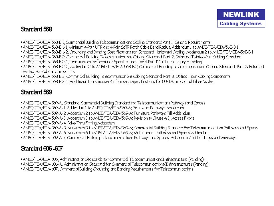
STANDARDS & CODES ANSI/TIA/EIA 568-B.x TIA/EIA 569 A TIA/EIA 606
TESTING PROCEDURES TSB-67 ANSI : American National Standards Institute EIA : Electronic Industries Alliance TIA : Telecommunications Industry Association Las comunicaciones en cobre pueden llegar a frecuencias límite alrededor de los 600 Mhz, alcanzando los umbrales de las frecuencias de 800 Mhz usadas por la telefonía celular. Los equipos activos brindarán comunicaciones eficaces con una tasa menor de errores y retransmisiones. Se prevé un incremento gradual al uso de la fibra óptica a nivel de usuario. Las tecnologias wireless irán solucionando sus principales problemas de ancho de banda y seguridad de acceso para ser cada vez mas comunes en las oficinas.

28
Standards

30
Telecommunications Standard for Commercial Buildings
TIA / EIA - 568 Telecommunications Standard for Commercial Buildings

31
TIA / EIA - 568 Parts TIA / 568 B.1 - Structured Cabling Guidelines
TIA / 568 B.2 - Specifications for Manufacturing UTP TIA / 568 B.3 - Specifications for Fiber Optics + Components

32
TIA / EIA - 568 Criteria Mandatory : must be implemented
Desirable : is a recommendation

33
TIA / EIA - 568 Purpose Specify Generic Cabling System
Multiuser, multiparty environment Makes easier installation planning Defines minimum performance levels

34
TIA / EIA - 568 Scope Commercial Buildings Campus Backbone
Area up to 1’000,000 m2 Population up to 50,000 usuarios Application for Voice, Data, Signaling, Video, Audio 10-year Life Cycle Horizon

35
TIA / EIA-568-B.1 Elements HORIZONTAL CABLING VERTICAL CABLING
WORK AREA TELECOMMUNICATIONS ROOM / CLOSET EQUIPMENT ROOM SERVICES ENTRY Telecomm Las comunicaciones en cobre pueden llegar a frecuencias límite alrededor de los 600 Mhz, alcanzando los umbrales de las frecuencias de 800 Mhz usadas por la telefonía celular. Los equipos activos brindarán comunicaciones eficaces con una tasa menor de errores y retransmisiones. Se prevé un incremento gradual al uso de la fibra óptica a nivel de usuario. Las tecnologias wireless irán solucionando sus principales problemas de ancho de banda y seguridad de acceso para ser cada vez mas comunes en las oficinas.

36
TIA / EIA – 568-B.1 Elements TR SE ER IC Building A Building B
Work Area Telecommunications Room Intermediate Closet Equipment Room Service Entry WA Building A Building B TR SE ER WA IC

37
TIA / EIA – 568-B.1 Elements HUB Voice Data Horizontal Cabling

38
TIA / EIA – 568-B.1 Elements Vertical Cabling

39
Work Area / Workstation
TIA / EIA – 568-B.1 Elements Space destinated to the users of peripheral equipment. As a rule of thumb an Area of 10 sq. Meter must be destinated for each Work Area. Work Area defines where to put the faceplates loaded with jacks or connectors to be user-administrated. Work Area / Workstation

40
TIA / EIA – 568-B.1 Elements Destinated to host all the IT processing equipment. This Area is to be used by the Servers, PBX and all the equipment related to the IT Processing. Areas are determined by the TIA/EIA 569 standard Depending upon the size and complexity of the installation it could performs also as a TELECOMMUNICATIONS ROOM. Equipment Room

41
Telecommunications Room
TIA / EIA – 568-B.1 Elements Destinated to Racks, Cabinets containing the Cross-connects and some networking equipment at the beginning of the Horizontal Cabling. Areas are determined by the TIA/EIA 569 standard Depending upon the size and complexity of the installation it could perform as a EQUIPMENT ROOM at the same time. Telecommunications Room

42
TIA / EIA – 568-B.1 Elements LAN Services Entry
Contains the Entry Cross-Connect that isolates external lines from internal LANs. Electrical protection, fuses and suppresors shall be considered at this point as required by the National Electrical Code. Define the Limit of Responsibilities for Third Party Outside Services. LAN Outside Services Services Entry

43
TIA / EIA – 568-B.1 Elements TR SE ER IC Building A Building B
Work Area Telecommunications Room Intermediate Closet Equipment Room Service Entry WA Building A Building B TR SE ER WA IC

44
TIA / EIA – 568-B.1 Horizontal Cabling Guidelines
Extends from Telecom Room to Work Area Includes : Cross-connects, Cabling, Connectors Optionally : MuTOA, Consolidation Points Maximum Length Channel Configuration (including Patch Cords) = 100 m Permanent Link (without Patch Cords) = 90 m Recommended number of outlets 2 outlets per Work Area as minimum 1 shall be CAT 3 or superior 1 shall be CAT 5E or superior 3 5 7 4 6 8 1 2
 = 100 m. Permanent Link (without Patch Cords) = 90 m. Recommended number of outlets. 2 outlets per Work Area as minimum. 1 shall be CAT 3 or superior. 1 shall be CAT 5E or superior")
45
TIA / EIA – 568-B.1 Cross-Connection
Links Cable Segments using Patch Cords or Wire Jumpers Could consist of Patch Panels or other IDC connecting devices Exists in 3 hierarchy levels : Horizontal XC, Intermediate XC, Main XC

46
TIA / EIA – 568-B.1 Horizontal Cabling Guidelines
Minimum consider the following Systems at Design Stage: Voice / Phone, Data, Video, Other (Fire Alarm, BAS, etc) Horizontal Cabling is the most extensive, hard to modify installation, thus select pathways and routes is critical over the entire life-cycle. Consider extra room for future growing and changes. Follows all the guidelines for Pathways and Space Use as per ANSI/EIA/TIA-569 A.
 Horizontal Cabling is the most extensive, hard to modify installation, thus select pathways and routes is critical over the entire life-cycle. Consider extra room for future growing and changes. Follows all the guidelines for Pathways and Space Use as per ANSI/EIA/TIA-569 A.")
47
TIA / EIA – 568-B.1 Horizontal Cabling Guidelines
Maximum distance covered by Horizontal Cabling is 100 meter. A maximum of 90 meter is allowed from Telecommunications Room to Work Area. Patch cord’s length shall no exceed 5 meter in each segment end. A total of 10 meter is permited for all Patch Cords over the Horizontal segment. Additional restrictions apply when using optional Consolidation Point or MuTOA configurations.

48
TIA / EIA – 568-B.1 Horizontal Cabling Guidelines
AT AT MIN: 5 m CT MIN: 15 m CP Consolidation Point (optional) AT MAX: 90 m STAR Topology
 AT. MAX: 90 m. STAR Topology.")
49
TIA / EIA – 568-B.1 Horizontal Cabling Guidelines
Optional Maximum One Consolidation Point per Horizontal Link. Minimum Distance from Telecommunications Room to Consolidation Point is 15 meter. Minimum Distance from Consolidation Point to Work Area is 5 meter. All connections at Consolidation Point shall be of the IDC type. Splices are forbidden on UTP or STP copper cables. Up to two (2) splices are allowed when using Optical Fiber.
 splices are allowed when using Optical Fiber.")
50
TIA / EIA – 568-B.1 Horizontal Cabling Guidelines
UTP cables must be terminated with its 4 pair completed connected at both ends of the cable. RJ45 jacks with Eight (8) conductors must be used for all Horizontal Terminations. All connectors shall be of the IDC kind termination. Shielded-jacket cables must connect the shield at one end only. When connecting both ends an unwanted antenna effect appears.
 conductors must be used for all Horizontal Terminations. All connectors shall be of the IDC kind termination. Shielded-jacket cables must connect the shield at one end only. When connecting both ends an unwanted antenna effect appears.")
51
TIA / EIA – 568-B.1 Horizontal Cabling Guidelines
All the cables routed and connected at the Work Area shall have a correspondent connection at the Telecommunications Room.

52
TIA / EIA – 568-B.1 Horizontal Cabling Guidelines
It is strongly recommended that Work Areas be attended from the closer Telecommunications Room located on the same floor. Do not install any electrical service inside the telecommunications conduit or raceways. Keep recommended distances between power circuits and devices and the bundles of communications cables. For Testing and Certification purposes Structured Cabling Systems ends when it is connected to an Active Equipment. Splitters, adapters and connectors other than RJ45 plugs are considered not part of the Structured Cabling Systems.

53
TIA / EIA – 568-B.1 Horizontal Cabling Guidelines
RECOMMENDED CABLES Twisted-pair, balanced, 4-pair, 100 Ohm : UTP - Unshielded Twisted-Pair ScTP – Screened Twisted Pair 2 Optical Fibers (Tx / Rx) : multimode 50 /125 um multimode 62,5/125 um RECOGNIZED CABLES ScTP with 150 ohm called: STP-A Hybrid Cables (UTP + FO) in one jacket, individually each cable shall meet ANSI/EIA/TIA-568-B.2
 : multimode 50 /125 um. multimode 62,5/125 um. RECOGNIZED CABLES. ScTP with 150 ohm called: STP-A. Hybrid Cables (UTP + FO) in one jacket, individually each cable shall meet ANSI/EIA/TIA-568-B.2.")
54
TIA / EIA – 568-B.1 Horizontal Cabling Guidelines
UTP - Unshielded Twisted-Pair Four (4) Balanced Pair cable 100 Ohms Characteristic Impedance Intereference Protection by Twisting the conductors Most used, most cost-effective Performance Categories 3 up to 16Mhz 5E up to 100Mhz 6 up to 250Mhz
 Balanced Pair cable. 100 Ohms Characteristic Impedance. Intereference Protection by Twisting the conductors. Most used, most cost-effective. Performance Categories. 3 up to 16Mhz. 5E up to 100Mhz. 6 up to 250Mhz.")
55
TIA / EIA – 568-B.1 Horizontal Cabling Guidelines
Multimode Optical Fiber: 50 um o 62.5 um / 125 um core/cladding Maximum Length: 90 Mts Uses LED as light source Wavelength / Modal Bandwidth 850 nm (3.5 db/km) / 200 Mhz-km 1300 nm (1.0 db/km) / 500 Mhz-km
 / 200 Mhz-km nm (1.0 db/km) / 500 Mhz-km.")
56
TIA / EIA – 568-B.1 Elements TR SE ER IC Building A Building B
Work Area Telecommunications Room Intermediate Closet Equipment Room Service Entry WA Building A Building B TR SE ER WA IC

57
TIA / EIA – 568-B.1 Vertical Cabling - Backbone
Includes interconnections between: Horizontal Cross-connects Intermediate Cross-Connects Main Cross-connects All the links between Horizontal Cablings and Backbone Cabling must use Cross-connection. MXC XC IC

58
TIA / EIA – 568-B.1 Vertical Cabling - Backbone
MXC IC XC HC Use Hierarchical Star Topology A maximum of two levels is permitted Star arrangement makes troubleshooting easier

59
TIA / EIA – 568-B.1 Vertical Cabling - Backbone
Interconnects all the Telecommunications Rooms with the Equipment Room Connect the Service Entry with the Backbone matrix Includes inter-building links in Campus configuration Bldg A Bldg B Bldg C

60
TIA / EIA – 568-B.1 Vertical Cabling - Backbone
Select the routes using the TIA/EIA-569A guidelines All cross connects shall be of the IDC type Optical Fiber could be spliced several times everytime Total Insertion Loss remains below the Maximum allowed Combined lenght of patch cord to not exceed 15 m Active equipment could be used to extend the range for the Vertical Cabling.

61
TIA / EIA – 568-B.1 Vertical Cabling - Backbone
Recognized Cables Multipair UTP de 22 – 24 AWG Optical Fiber Multimode Optical Fiber Single-mode Distancias Máximas: UTP 800 m - Voice UTP 90 m - Data Multimode 2000 m Single-mode 3000 m

62
TIA / EIA – 568-B.1 Backbone Distances
HC A ES B IC MC C Horizontal Cross-connect HC Intermediate X-connect IC Main Cross-connect MC Fiber Single-mode Fiber Multimode UTP Balanced - DATA UTP Balanced - VOICE 800 90 2000 3000 300 500 1700 2700

63
TIA / EIA – 568-B.1 Vertical Cabling - Backbone
Optical Fiber Single-mode: 8.3 um / 125 um core/cladding Distance 3,000 m (50 Km in telephony) Use LASER emitters Wavelenght / Bandwidth 1310 nm (1.0 db/km) / MHz-km “unlimited” 1383 nm (1.0 db/km) / MHz-km “unlimited” 1550 nm (1.0 db/km) / MHz-km “unlimited”
 Use LASER emitters. Wavelenght / Bandwidth nm (1.0 db/km) / MHz-km unlimited 1383 nm (1.0 db/km) / MHz-km unlimited 1550 nm (1.0 db/km) / MHz-km unlimited")
64
TIA / EIA – 568-B.1 Telecommunication Room
Area destinated to Telecomunications Services Only Its main function is to host Cabling endings and inter-connects Host all the “Cross Connects” : Horizontal – Active Equipment Horizontal - Vertical (voice connections) Vertical – Active Equipment Vertical - Vertical (Intermediate Connects) Dimensions and specifications by EIA/TIA-569 A
 Vertical – Active Equipment. Vertical - Vertical (Intermediate Connects) Dimensions and specifications by EIA/TIA-569 A.")
65
TIA / EIA – 568-B.1 Work Area Designed for user flexibility
Uses a minimum of 2 outlets per each Workstation Permits optionally the use of MuTOA (Multiuser Telecomm Outlet Assemblies) The use of MuTOA use a special formula to compute the maximum patch cord’s length. For design purposes consider an Area of 10 sq. Meter for each Work Area.
 The use of MuTOA use a special formula to compute the maximum patch cord’s length. For design purposes consider an Area of 10 sq. Meter for each Work Area.")
66
TIA / EIA – 568-B.1 Equipment Room
Must contain the main “HUB” Could contain the MCC and share functions of Telecommunication’s Room in the same space. Contains the Servers, PBX, Telecom Equipment, all the IT equipment. Generally requires a controlled temperature, air humidity, power stability, safety, etc. Must be designed following TIA/EIA-569 Guidelines

67
TIA / EIA – 568-B.2 Cabling Components
MEDIA : UTP, coaxial, multi-pair, optical fiber CONNECTORS : jacks, patch panels, plugs ORGANIZERS : vertical, horizontal, front/rear SUPPORT : cabinets, racks, boxes, shelves Las comunicaciones en cobre pueden llegar a frecuencias límite alrededor de los 600 Mhz, alcanzando los umbrales de las frecuencias de 800 Mhz usadas por la telefonía celular. Los equipos activos brindarán comunicaciones eficaces con una tasa menor de errores y retransmisiones. Se prevé un incremento gradual al uso de la fibra óptica a nivel de usuario. Las tecnologias wireless irán solucionando sus principales problemas de ancho de banda y seguridad de acceso para ser cada vez mas comunes en las oficinas.

68
TIA / EIA – 568-B.2 Cabling Components
Requisites for Connectors: Materials Smoke Emission Dimensions and tolerances Electrical characteristics Performance by TIA/EIA-568-B.3 Marking CAT 5, 6, OFNR, etc Connect / Disconnect # of cycles

69
TIA / EIA – 568-B.2 Cabling Components
Requisites for the cable: Conductor Materials Jacket materials Fire Resistance Properties Dimensions and Tolerances Wire section area AWG Electrical characteristics Performance by TIA/EIA-568-B.3 Marking CAT 5, 6, OFNR, etc

70
TIA / EIA – 568-B.2 Cabling Components
Connecting Devices in Structured Cabling Systems shall be of the IDC (Insulation Displacement Connection) type. Including: Jacks in Outlets Jacks in Patch Panels Connecting Blocks Consolidation or Transition Points
 type. Including: Jacks in Outlets. Jacks in Patch Panels. Connecting Blocks. Consolidation or Transition Points.")
73
TIA / EIA - 568 Media : TWISTED PAIRS

74
Bandwidth, Categories & Classes
Bandwidth (MHz) ANSI/TIA/EIA Data Rate Aplication 1 CAT 1 64 kbps POTS, EIA 232 10 CAT 2 4 Mbps Token Ring 16 CAT 3 10 Mbps Ethernet 20 CAT 4 25 Mbps ARCNet, ATM 100 CAT 5 100 Mbps Fast Ethernet CAT 5E 155 Mbps 155 ATM 250 CAT 6 Class E Gigabit Ethernet 600* CAT 7* Class F
 ANSI/TIA/EIA. Data Rate. Aplication. 1. CAT kbps. POTS, EIA CAT 2. 4 Mbps. Token Ring. 16. CAT Mbps. Ethernet. 20. CAT Mbps. ARCNet, ATM CAT Mbps. Fast Ethernet. CAT 5E. 155 Mbps. 155 ATM CAT 6. Class E. Gigabit Ethernet. 600* CAT 7* Class F.")
75
TIA / EIA – 568 UTP Cable – 4 Pairs
3 5 7 4 6 8 1 2

76
TIA / EIA – 568-B.1 Standard Terminations
Par 3 Par 1 Par 2 Par 4 T568A Par 2 Par 1 Par 3 Par 4 T568B

77
TIA / EIA – 568-B.1, B.2 Cabling Components
Patch Cords shall use stranded cables Must match the same Category as the Horizontal UTP Cable and connectors. Must be NEWLINK in order to included them for the NEWMAX 25-years Warranty Performance Limits are the same that those who corresponds to UTP solid conductors except by the Insertion Loss / Attenuation that is greater.

78
TIA / EIA – 568-B.1 Attenuation
Decay of the signal power measured by comparing Input against Output levels. Represents the power of signal available at the far end of the cable. Is expressed in decibels (dB). P = -10 log S2 S1 where S2 < S1 S1 S2
. P = -10 log. S2. S1. where S2 < S1. S1. S2.")
79
TIA / EIA – 568-B.1 Attenuation
Each 3 dB step power doubles Each 10 dB step power multiplies by 10 Example: Output Level = 0 dB Media Attenuation = -25 dB Received Signal (%) = 0,31% !! P dB 100% 50% 25% 12,5% 6,25% -3 -6 -9 -12
 = 0,31% !! P. dB. 100% 50% 25% 12,5% 6,25%")
80
TIA / EIA – 568-B.1 Attenuation
Depends on : Media Type Transmission Frequency Temperature (mainly with UTP) Geometry, Shape (both UTP and Fiber) Conductor Section (AWG), Core Type (FO) Electrical Characteristics Humidity Other
 Geometry, Shape (both UTP and Fiber) Conductor Section (AWG), Core Type (FO) Electrical Characteristics. Humidity. Other.")
81
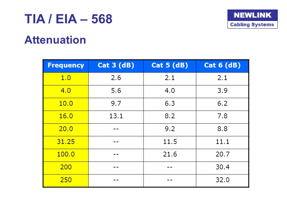
TIA / EIA – 568 Attenuation Frequency Cat 3 (dB) Cat 5 (dB) Cat 6 (dB)
1.0 2.6 2.1 4.0 5.6 3.9 10.0 9.7 6.3 6.2 16.0 13.1 8.2 7.8 20.0 -- 9.2 8.8 31.25 11.5 11.1 100.0 21.6 20.7 200 30.4 250 32.0
82
TIA / EIA – 568 Attenuation dB ATTENUATION Frequency (MHz) 50 100 250
50 100 250 150 200 Frequency (MHz)
")
83
TIA / EIA – 568-B.1 Next-End CrossTalk: NEXT
Unwanted Signal coupling between adjacent pairs Is expressed in dB Diminishes with the Frequency Crosstalk exists only in metallic conductors Larger NEXT values indicates more capacity to transmit higher power levels without interference with other pairs NEXT failures founded during Testing process correspond to cable and connector terminations mainly

84
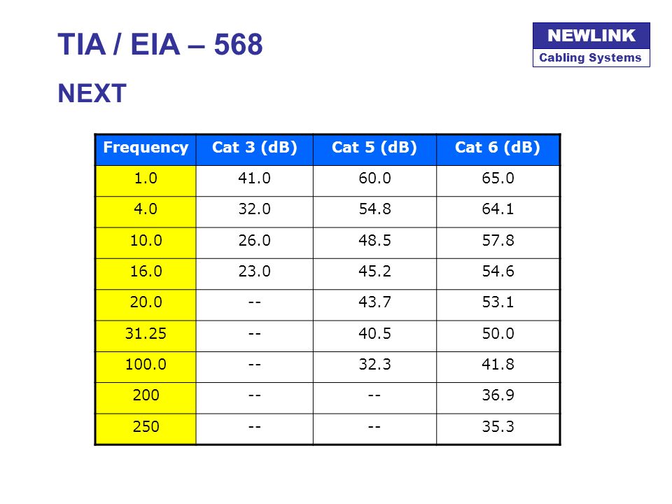
TIA / EIA – 568 NEXT Frequency Cat 3 (dB) Cat 5 (dB) Cat 6 (dB) 1.0
41.0 60.0 65.0 4.0 32.0 54.8 64.1 10.0 26.0 48.5 57.8 16.0 23.0 45.2 54.6 20.0 -- 43.7 53.1 31.25 40.5 50.0 100.0 32.3 41.8 200 36.9 250 35.3
85
TIA / EIA – 568 NEXT dB NEXT 50 100 250 150 200 Frequency (MHz)
")
86
TIA / EIA – 568 Available Bandwidth
dB NEXT ACR ATTENUATION 50 100 250 150 200 Frequency (MHz)
")
87
Technical Specifications for Field Testing
TIA / EIA TSB-67 Technical Specifications for Field Testing

88
TIA / EIA TSB-67 Introduction
Define the different Tests that are required for UTP and FO Documents Quality Controls Designed for the TIA/EIA-568 Installations NOTE Formally the requirements for the TSB-67 have been incorporated to the body of the TIA/EIA-568.B-2 standard, but it is mentioned frequently as a reference.

89
TIA / EIA TSB-67 Scope TSB 67 Specifies the Performance requirements for a Link Defines: Test Models Test Procedures Results Interpretation Tester automatically contrast results with laboratory parameters

90
TIA / EIA TSB-67 Applicability
Suitable for : 4-Balaced Pairs type UTP, 100 Ohms 4-Balaced Pairs type ScTP, 100 Ohms Cable de 4 pares Only applicable for Horizontal Cabling Specific Tests exist for each Category of cable: 3, 5E, 6

91
TIA / EIA TSB-67 The Points of Failure
Cabling Systems NEWLINK TIA / EIA TSB-67 The Points of Failure 1 A B 15 16 14 2 3 5 6 4 7 8 9 10 11 POINT OF FAILURE BY ORIGIN: INSTRUMENTS A, B PATCH CORDS 1, 2, 3 – 9, 10, 11 WORKMANSHIP 5 , 7 PATCH PANEL / JACKS 4 , 8 CABLE 6

92
TIA / EIA TSB-67 The Workmanship on the Patch Panel
Cabling Systems NEWLINK TIA / EIA TSB-67 The Workmanship on the Patch Panel Excesive untwist length Bad color addressing Different color scheme for the same cable ends Poor Insertion / IDC

93
TIA / EIA TSB-67 The Workmanship on the RJ-45 Jack
Cabling Systems NEWLINK TIA / EIA TSB-67 The Workmanship on the RJ-45 Jack Excessive untwisted T568A Scheme T568B Scheme Poor Insertion / IDC

94
TIA / EIA TSB-67 Bandwidth, Categories & Classes
Bandwidth (MHz) ANSI/TIA/EIA Data Rate Application 1 CAT 1 64 kbps POTS, EIA 232 10 CAT 2 4 Mbps Token Ring 16 CAT 3 10 Mbps Ethernet 20 CAT 4 25 Mbps ARCNet, ATM 100 CAT 5 100 Mbps Fast Ethernet CT 5E 155 Mbps 155 ATM 250 CAT 6 Class E Gigabit Ethernet 600* CAT 7* Class F
 ANSI/TIA/EIA. Data Rate. Application. 1. CAT kbps. POTS, EIA CAT 2. 4 Mbps. Token Ring. 16. CAT Mbps. Ethernet. 20. CAT Mbps. ARCNet, ATM CAT Mbps. Fast Ethernet. CT 5E. 155 Mbps. 155 ATM CAT 6. Class E. Gigabit Ethernet. 600* CAT 7* Class F.")
95
TIA / EIA TSB-67 Testing Practices
Standard Models : Permanent Link Channel Test

96
TIA / EIA TSB-67 Testing Practices
Permanent Link Cross Connect UTP Cable permanently installed Outlet Jacks Channel Test All of the Above plus: Patch cord in the Cross-connect Patch cable used in the Work Area

97
TIA / EIA TSB-67 Testing Practices
PERMANENT LINK Telecomm. Closet Work Area XC Fp 90 m Use the Instrument Patch Cords

98
Use the Patch Cords destinated to such specific Work Area
TIA / EIA TSB-67 Testing Practices CHANNEL TEST Telecomm. Closet Work Area XC Fp 90 m Use the Patch Cords destinated to such specific Work Area

99
TIA / EIA TSB-67 Testing Practices
Cabling Systems NEWLINK TIA / EIA TSB-67 Testing Practices During Installation Check for continuity inmediatly after connecting both ends of the cable More than 80% of the fails corresponds to an unproper termination (open wires, shorted wires, swapping pairs) After Job Conclusion Test First for Permanent Link at corresponding Category If results are OK Test then for Channel configuration Use current calibrated instruments only
 After Job Conclusion. Test First for Permanent Link at corresponding Category. If results are OK Test then for Channel configuration. Use current calibrated instruments only.")
100
TIA / EIA TSB-67 Testing Practices
Cabling Systems NEWLINK TIA / EIA TSB-67 Testing Practices Testing CAT 6 and CAT 5E links requires improved accuracy from portable certification equipment. Performance Level III Field Testers are required. It is very important to consider that equipment must be in optimal operating conditions to get valid measurements. Set Calibration and good condition for connectors or adapters is a must.

101
TIA / EIA TSB-67 Definitions
Wire Map / Mapping Check straight termination pin-to-pin. Verify: Proper pin termination at each end, Continuity to the remote end, Shorts between any two or more conductors, Crossed pairs, Split pairs, Reversed pairs, Shorted pairs. Pair 2 1 2 T568A T568B Pair 3 3 4 5 6 7 8 Pair 1 Pair 4

102
TIA / EIA TSB-67 Definitions
ScTP Shield Continuity This Test applies only for Shielded Cables. The test consist in verify the consistency for the metallic shield covering the telecommunications pairs.

103
TIA / EIA TSB-67 Definitions
Length / NVP Based Depending upon the Model under Test, it allows two different results: 100 m including all the elements from patch cord to patch cord 90 m correspondent only to the Permanent Link segment Permanent Link Test Maximum 90 m Complete Channel Test Maximum m

104
TIA / EIA TSB-67 Definitions
Insertion Loss (Attenuation) Is the measure representing the level of signal loss along the different elements “inserted” in the link. Insertion Loss includes the losses of the patch cords when running the Channel Test. It is expressed in terms of Decibels (dB) for easy comparission. -L dB -L dB 6 2 -L dB -L dB 3 4 -L dB -L dB -L dB 1 5 7 Insertion Losses = E Li <i=1 ..n>
 Is the measure representing the level of signal loss along the different elements inserted in the link. Insertion Loss includes the losses of the patch cords when running the Channel Test. It is expressed in terms of Decibels (dB) for easy comparission. -L. dB. -L. dB L. dB. -L. dB L. dB. -L. dB. -L. dB Insertion Losses = E. Li <i=1 ..n>")
105
TIA / EIA TSB-67 Definitions
CROSS-TALK When a current flows through a wire, an electromagnetic field is created which can interfere with signals on adjacent wires. As frequency increases, this effect becomes stronger. Each pair is twisted because this allows opposing fields in the wire pair to cancel each other. The tighter the twist, the more effective the cancellation and the higher the data rate supported by the cable. Maintaining this twist ratio is the single most important factor for a successful installation. Interferent Magnetic field is proportional to the current in the conductor and grows with the frequency

106
TIA / EIA TSB-67 Definitions
CROSS-TALK Cross-Talk is the interference transfered from a telecommunication’s pair to other adjacent pairs. Those pairs may belong to the same cable in a multi-pair cable or to a bundle of cables (allien cross-talk). Cross-Talk depends upon the transmission power level, cable geometry and the impedance of the telecommunication conductors. It also increases with an increase of frequency and length (when it is evaluated in the far-end of the cable). It is expressed in dB showing the relationship between the received-to-transmitted signal ratio. NEXT FEXT TX Signal Weaked Signal Coupled Interference
. Cross-Talk depends upon the transmission power level, cable geometry and the impedance of the telecommunication conductors. It also increases with an increase of frequency and length (when it is evaluated in the far-end of the cable). It is expressed in dB showing the relationship between the received-to-transmitted signal ratio. NEXT. FEXT. TX Signal. Weaked Signal. Coupled Interference.")
107
TIA / EIA TSB-67 Definitions
NEXT / Near End Cross-Talk Measures the ratio between unwanted coupled interference and intended to transmit signal. It is measured showing the effect of each pair over the others assuming that such effect is symmetrical from pair-A to pair-B as from pair-B over pair-A. NEXT is evaluated in both cable ends. Pair 2 1 2 3 4 5 6 7 8 Pair 1 Pair 3/1 Pair 3 MEASUREMENT Pair 2/1 Pair 4/1 Pair 4/2 Pair 3/2 Pair 4/3 Tx

108
TIA / EIA TSB-67 Definitions
PS-NEXT / Powersum Power sum Near-End Crosstalk adds the effect caused by each transmission over 1 pair simultaneously. This is important to consider since Gigabit Ethernet because it utilizes the 4-pairs in a UTP cable to aggregate the required throughput and transmission is full-duplex. Once again it must be evaluated at both cable ends. Pair 2 1 2 3 4 5 6 7 8 Pair 1 Pair 3/1 + Pair 3 SIMULTANEOUS EFFECT Pair 2/1 Pair 4/1 Pair 4/2 Pair 3/2 Tx Pair 1/2 Pair 4/3 Pair 2/3 Pair 1/3 Pair 4 Pair 3/4 Pair 2/4 Pair 1/4

109
TIA / EIA TSB-67 Definitions
FEXT / Far End Cross-Talk Far-End Crosstalk evaluates the effect of transmitted signal at the other end over an adjacent cable. It is important because signal diminishes with the distance but interference cumulates power along the cable resulting in a wider and higher interference at the far end against a weak transmitted signal. Pair 2 1 2 3 4 5 6 7 8 Pair 1 Pair 3/1 Pair 3 MEASUREMENT Pair 2/1 Pair 4/1 Pair 4/2 Pair 3/2 Tx Pair 1/2 Pair 4/3 Pair 2/3 Pair 1/3 Pair 4 Pair 3/4 Pair 2/4 Pair 1/4

110
TIA / EIA TSB-67 Definitions
PS-FEXT / Powersum Evaluates the simultaneous effect of FEXT adding the interference coming from each pair. With Powersum evaluation the combined effect is measured simulating one of the worst operating conditions. 1 2 3 4 5 6 7 8 Pair 1 Pair 3/1 + SIMULTANEOUS EFFECT Pair 2/1 Pair 4/1 Tx

111
ACR = NEXT (dB) - ATTENUATION (dB)
TIA / EIA TSB-67 Definitions ACR / Attenuation to Cross-talk Ratio ACR is a computed value resulting from measured NEXT and ATTENUATION : ACR = NEXT (dB) - ATTENUATION (dB) ACR brings a reference for the MAXIMUM SIGNAL LEVEL that is possible to transmit in order to get an enough signal level at the remote cable end. NEXT stands here to limit this MAXIMUM inside tolerances; while ATTENUATION demands more signal power to compensate the signal reduction along runnings. ACR establish the real Media capability to carry Signals, and shows how this capability is affected in function of Transmission Frequencies .
 - ATTENUATION (dB) ACR brings a reference for the MAXIMUM SIGNAL LEVEL that is possible to transmit in order to get an enough signal level at the remote cable end. NEXT stands here to limit this MAXIMUM inside tolerances; while ATTENUATION demands more signal power to compensate the signal reduction along runnings. ACR establish the real Media capability to carry Signals, and shows how this capability is affected in function of Transmission Frequencies .")
112
TIA / EIA TSB-67 Definitions
ACR: how much stronger the signal could be than the background noise at the Transmitter end. Frequency (MHz) dB 50 100 250 150 200 ACR NEXT ATTENUATION
 dB ACR. NEXT. ATTENUATION.")
113
ELFEXT = FEXT (dB) - ATTENUATION (dB)
TIA / EIA TSB-67 Definitions ELFEXT / Equal Level Far End Cross-Talk ELFEXT is another computed magnitud based on FEXT and ATTENUATION: ELFEXT = FEXT (dB) - ATTENUATION (dB) It is derived by subtracting the attenuation of the disturbing pair from the Far End Crosstalk (FEXT) this pair induces in an adjacent pair. This normalizes the results for length. El PS-FEXT considers the cumulative effect of simultaneous transmission over the 4-pair.
 - ATTENUATION (dB) It is derived by subtracting the attenuation of the disturbing pair from the Far End Crosstalk (FEXT) this pair induces in an adjacent pair. This normalizes the results for length. El PS-FEXT considers the cumulative effect of simultaneous transmission over the 4-pair.")
114
TIA / EIA TSB-67 Definitions
PROPAGATION DELAY 550 ns 580 ns 510 ns 535 ns When a signal propagates through a conductor it does not travel at the theoretical c: speed of light in the vacuum, but at a NPV Net propagation Velocity expressed as a factor of such c. Typically a NPV between 65% to 90% is obtained over copper twisted pairs. Testers measures the total amount of time taked by a signal to complete its travel end-to-end.

115
TIA / EIA TSB-67 Definitions
DELAY SKEW Because each pair has a different total length, the delay obtained from each pair differs from each other. This parameter evaluates the difference between the faster and the slower pairs. It is specially important for transmission protocols that use the 4 pairs in a full-duplex context. 550 ns 580 ns 510 ns 535 ns Delay skew = 580 – 510 = 70 ns

116
TIA / EIA TSB-67 Definitions
RETURN LOSS To transfer energy from one media to other it is neccesary that a proper impedance matching exists between the two medias. As perfect matching is pure theory, normally the most of the signal pass ahead and a small part is reflected. This reflection is evaluated as Return Loss. This test checks how good enough is the coupling between the UTP cable and the RJ-45 connectors at the cable end. reflected

117
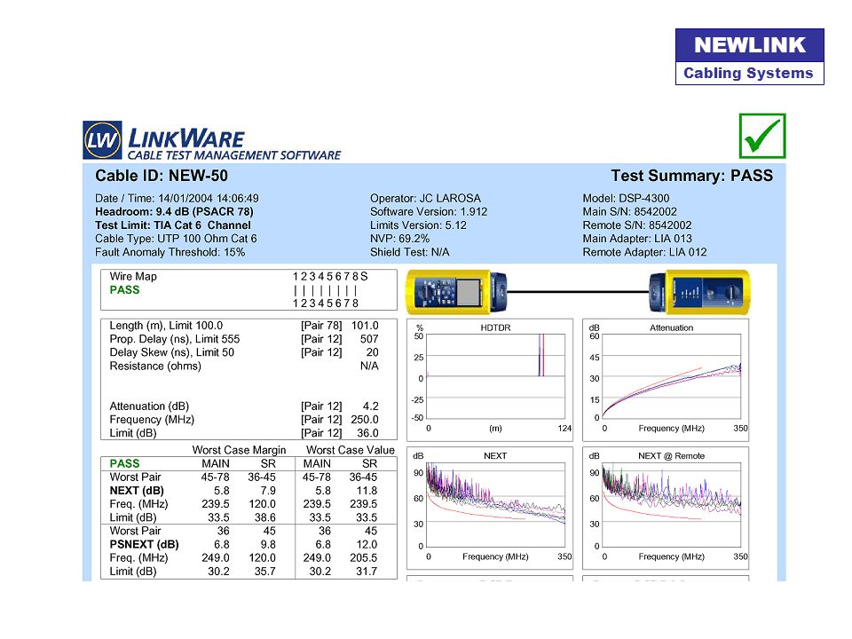
TIA / EIA TSB-67 PERFORMANCE TEST SUMMARY
WIRE MAP SHIELD CONTINUITY LENGTH INSERTION LOSS NEXT (pair-to-pair) PS-NEXT Loss FEXT (pair-to-pair) PS-FEXT Loss PROPAGATION DELAY DELAY SKEW RETURN LOSS PS-ACR PS-ELFEXT
 PS-NEXT Loss. FEXT (pair-to-pair) PS-FEXT Loss. PROPAGATION DELAY. DELAY SKEW. RETURN LOSS. PS-ACR. PS-ELFEXT.")
120
NEWMAX® 25-year Limited Warranty REQUIREMENTS
Certified Installer Participation Complete Data about Project Backbone Diagram CAD drawings showing office’s layout Pertinent Connection Schemes List of Materials under Warranty Test Results file (100%) Documents should be recorded in a CD-ROM and mailed to your NEWMAX Distributor
 Documents should be recorded in a CD-ROM and mailed to your NEWMAX Distributor.")
121
NEWMAX® 25-year Limited Warranty DESCRIPTION
25-Year materials replacement of defectives 100% existing applications by TIA/EIA 568 based on CAT Damage by thirds, poor environmental and humid/dusty conditions void the expressed Limited Warranty

Similar presentations